4.1.7.1. Carbon Fiber Epoxy Resin Laminates – Basic Laminate Strength
The method shown in this chapter is solely concerned with laminate failure, not lamina failure. Lamina failure criteria traditionally works best when a pristine laminate is considered. For aircraft primary structure a defined project and material specific level of damage must be assumed to be present in the laminate (the Allowable Damage Limit, or ADL). At this level of damage, the structure must display ultimate strength at the worst environmental condition.
The failure criteria approach that the author has found to be the most robust and reliable is the biaxial strain envelope approach.
This has been used by several OEMs on several aircraft programs with success as part of their certification programs. The derivation and route through to choosing this method is proprietary to those organizations. A history of how this approach has been developed is given in (![]() NASA Conference Publication 3087, Part 2, 1990).
NASA Conference Publication 3087, Part 2, 1990).
This history mirrors the author’s own experience developing a certification methodology for a composite aircraft OEM.
The pertinent section of (![]() NASA Conference Publication 3087, Part 2, 1990) is written by the exceptional L. J. Hart-Smith. It is not the intention to repeat his development of this approach below. It is well documented in the reference. I have attempted to give an overview. For clarification, the reference should be consulted.
NASA Conference Publication 3087, Part 2, 1990) is written by the exceptional L. J. Hart-Smith. It is not the intention to repeat his development of this approach below. It is well documented in the reference. I have attempted to give an overview. For clarification, the reference should be consulted.
Note that the original L.J Hart-Smith definition applied to fiber failure only. In the following section, the adaptation of the method to matrix failure modes is shown.
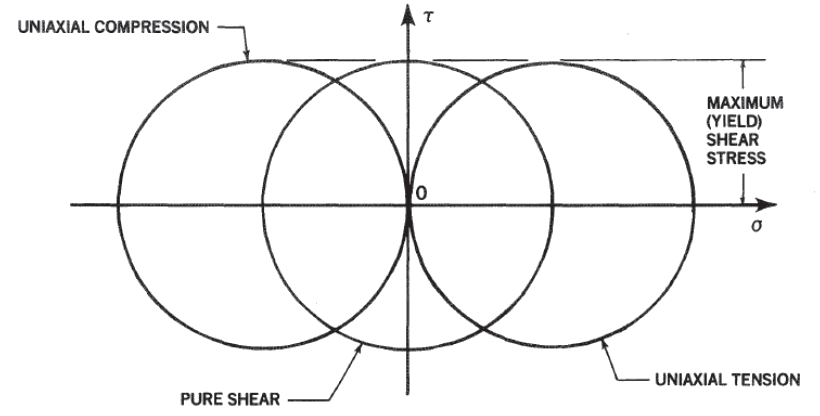
Most engineers are familiar with Mohr’s circle as a visual expression of the stress or strain state of an isotropic material:
 NASA Conference Publication 3087, Part 2, 1990)
 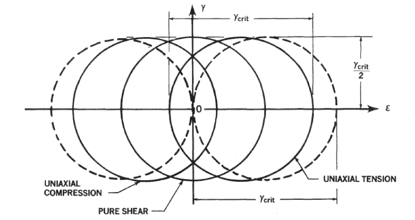 NASA Conference Publication 3087, Part 2, 1990)
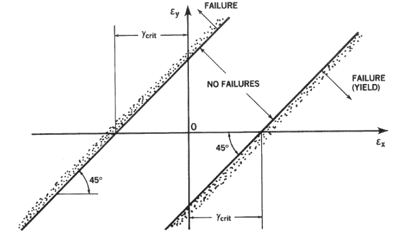
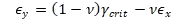
 Unlike metallic materials, laminate composites are more prone to develop early failure modes as an interaction of the longitudinal and transverse strength of the laminate. It is, therefore, more appropriate to represent the plane strain state of the laminate in terms of the two principal strains. In this case, the strain limits can be plotted as lines at 45 degrees. The lines defined by the relationship ϵₓ-ϵᵧ=γ꜀ᵣᵢₜ are shown in Figure 4.1.7‑3:
 NASA Conference Publication 3087, Part 2, 1990)
 Additional cut offs can be added to the plot representing the following relationships:
 NASA Conference Publication 3087, Part 2, 1990)Materials
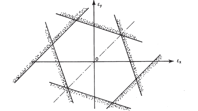
 Figure 4.1.7‑4 can be tidied up and shown with a definition of each region of the envelope as a useful summary in the following figure:
 NASA Conference Publication 3087, Part 2, 1990)
 The precise shape of the six-sided envelope depends on the value of (Poisson’s ratio). It can be derived that the value of that gives an equal sided hexagon for an isotropic material is 0.2679, which is close to the typical value for most metals.
This method so far has developed a failure envelope for an isotropic material. The next section deals with how this envelope is modified to apply to a composite laminate material.
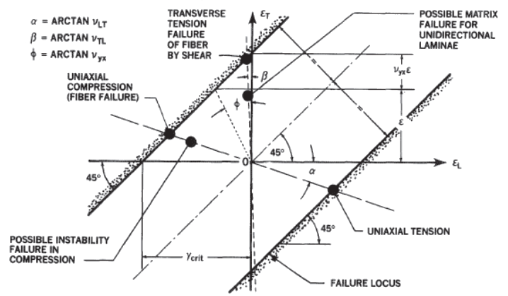
The same development will be shown for an orthotropic material considering only fiber failure:
The next step is to generalize the preceding analysis to orthotropic layers. The failure criterion to be derived should actually refer to the fiber, for fiber-dominated failures, not the lamina. However, the fibers and matrix obviously share a common strain along the fiber axis. For the usual case, in which strong, stiff fibers are embedded in a soft matrix, it is possible to bypass the micromechanical calculations relating the transverse strains of the fiber to those of the lamina because of the greater criticality of the fiber failure criterion.
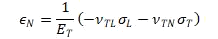
It is assumed again that there are no normal or through-the-thickness shear stresses acting on the laminate. Using the subscripts L, T, and N to denote the longitudinal, transverse (in-plane), and normal directions, respectively. The strains for transversely isotropic materials read as follows when the axis of symmetry is longitudinal:
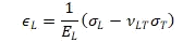
And:
For a uniaxial load along the fibers, with neither lateral nor normal applied stress, the axial strain in both the fiber and lamina will be at failure and the associated lateral and normal strains will be -νᴌᴛϵ₀ in the lamina. The corresponding orthogonal strain in the fiber, which can be presumed to have a different Poisson’s ratio from the homogenized lamina, is undefined. However, for typical carbon epoxy composites, the similarity of the Poisson’s ratio νᴌᴛ for the unidirectional lamina and for an isotropic resin matrix, implies that the corresponding Poisson’s ratio for the fiber must also be similar.
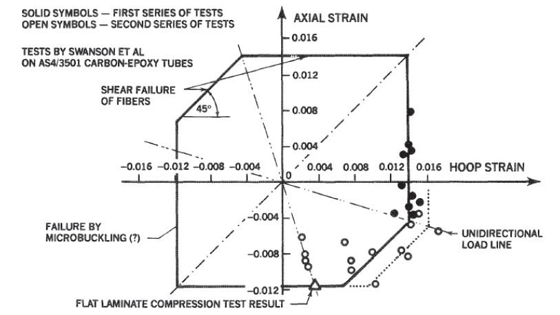
Figure 4.1.7‑4 shows the traces of these uniaxial load lines, in tension and compression, on the ϵᴌ – ϵᴛ in-plane strain plane. If the tension and compression strengths are the same, it is possible to locate the 45-degree sloping shear-failure lines on which the uniaxial failures are represented by individual points.
If the tensile and compressive strengths differ, the numerically greater value defines both shear-failure lines, as shown in Figure 4.1.7‑6, while the lesser strength defines a cut off due to some other failure mechanism, such as micro-buckling under compression.
For a uniaxial in-plane load perpendicular to the fibers, a different Poisson’s ratio,vₜₗ , is involved and the uniaxial load line is no longer symmetric as it was for isotropic materials in Figure 4.1.7‑4. The traces of this unidirectional load condition can be added to Figure 4.1.7‑6, and wherever they cross the shear-failure lines denotes the points of failure of the fibers.
Note:With unidirectional laminae, the matrix may fail prematurely under transverse tension at a lower strain, but that is normally suppressed for any typical cross-plied structural laminate and may be considered as a special case.
 NASA Conference Publication 3087, Part 2, 1990)
 It is apparent that the same critical shear strain loads through the entire region of interest since the sum of the longitudinal and orthogonal shear strains is always:
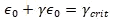
No matter what the value of Poisson’s ratio for any particular cross-plied laminate.
Adding limits to the strain envelope for arbitrary tension and compression strengths and failure envelopes for orthogonal layers of orthotropic materials the following envelope is developed.
 NASA Conference Publication 3087, Part 2, 1990)
 This method shows good correlation for the intact laminate in the referenced paper. In the introduction, the following guidance is given: “Premature matrix failures can also be covered by appropriately truncating the fiber failure envelope”.
As discussed previously, composite laminates for aircraft primary structure must be able to sustain ultimate load with damage up to the barely visible level (BVID).
It is common to use CAI (Compression After Impact) strength for the limit compression strength and open hole tension (OHT) for the limit tension strength. For a carbon fiber laminate, the envelope is significantly truncated when compared to the pristine laminate strength:
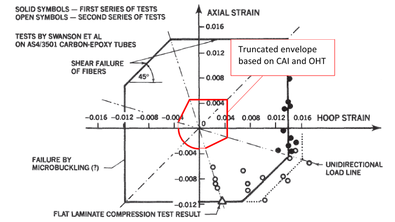
It can be seen from the figure above that the Kt effect from damage and features such as holes, superimposed over the effects of worst-case environmental conditioning gives a significant, if not radical, reduction in strength over the pristine laminate.
It is important that the large difference between the pristine laminate strength and the no-growth strain limit is understood. This accounts for the severe reduction or complete absence of weight saving when changing from aluminum structure to composite structure.
This underlines the potential benefits of composite structure:
- If the assemblies are designed correctly there can be a large reduction in manufacturing cost.
- If the structure is analyzed and sized correctly the airframe should not suffer from any damage growth in service.
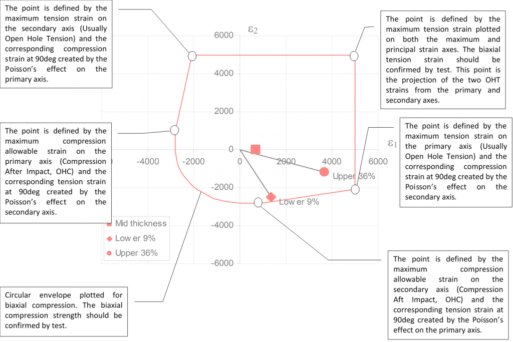
The boundary of the worst case (no growth) design strain envelope is defined as shown on the next page.
Depending on the available budget and schedule these metrics (CAI, OHT) can be developed for multiple layups and all environmental conditions.
In general, it can be expected that the layups closest to quasi-isotropic that use woven cloth product will give the greatest CAI and OHT strain limits. The laminates with greater anisotropy and with UD rather than woven fiber product will give the lowest strain limits.
For initial conservative sizing, it can be assumed that the laminate with the most aligned UD plies at ETW condition will give you the most conservative laminate allowable strains. Initial testing can concentrate on these type of test panels and as time and budget allows, the less critical laminate configurations can be tested.
The analysis can then be refined to target specific laminates with allowables developed for that specific layup. This will allow for greater weight saving.
Note that this approach is only applicable to solid laminates and not for cored laminates.
Several ‘high performance’ aircraft have been certified with cored composite laminates used for primary structure. (![]() DOT/FAA/AR-99/49, 1999) is a review of some of these aircraft and gives some guidance for damage tolerance of cored laminate structure.
DOT/FAA/AR-99/49, 1999) is a review of some of these aircraft and gives some guidance for damage tolerance of cored laminate structure.
The following points can be superimposed over the envelope described on the previous page:
A line can then be plotted from the origin of the graph though the upper and lower plotted strain points to the perimeter of the biaxial strain envelope.
- The distance from the origin to the plotted strain point (L1) can be determined.
- The distance from the origin through the plotted strain point to the perimeter of the envelope (L2) can be determined.
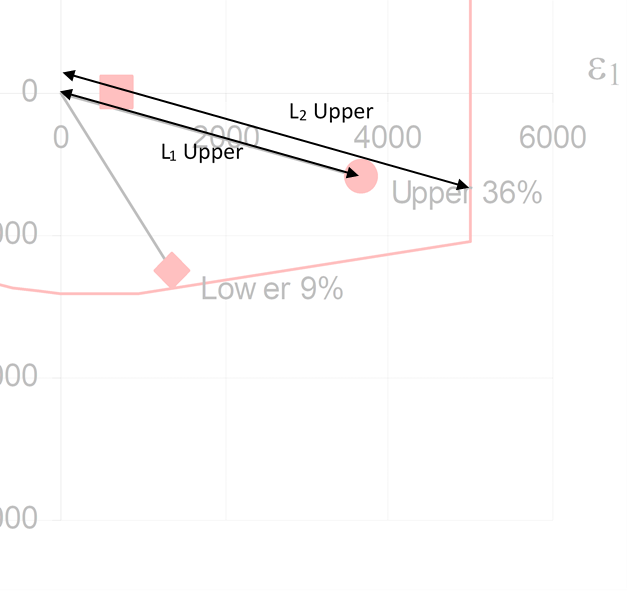
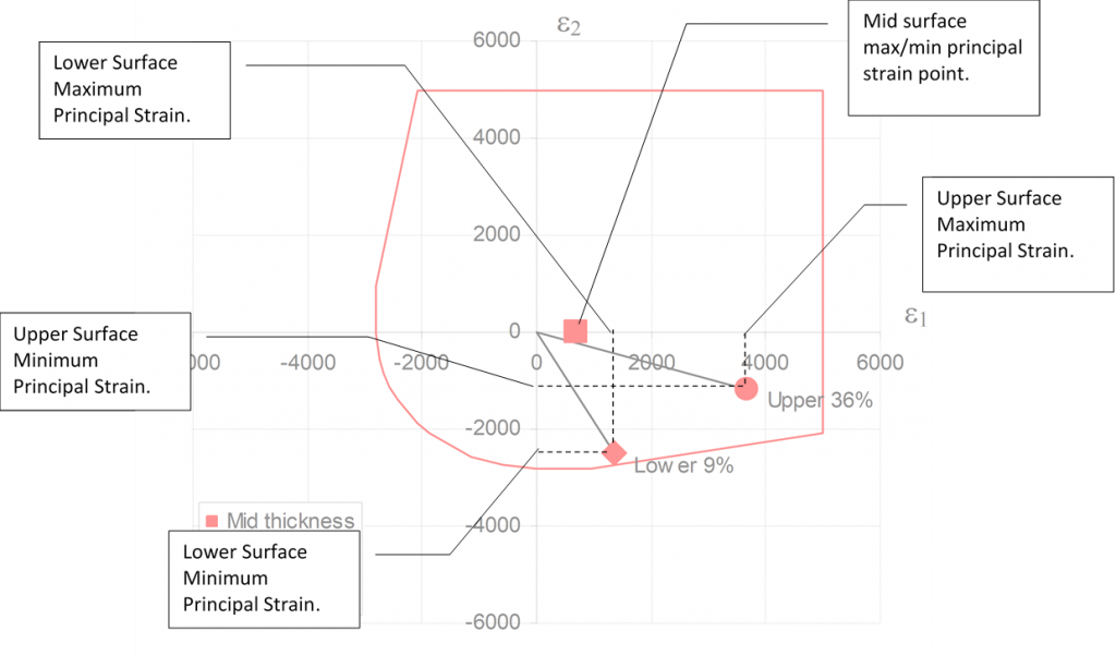
With this information, the margin of safety can be calculated. For the upper surface:

he spreadsheet automatically calculates this margin of safety for the upper and lower surfaces.
The mid surface margin of safety is never less in magnitude than the upper or lower surface margin of safety.
This method is available in this spreadsheet:
This spreadsheet compares the calculated applied strains with a range of allowable strain values. These can be input for different environmental conditions or for any other variation and the envelope can be selected for the margin of safety calculation. If only one condition is to be considered the CAI values can be set to the same value for all environmental conditions and OHT values can be set to the same OHT strength for all environmental conditions.