Composite materials are by definition made up of different types of materials. The common composites used in aircraft design are laminate composites. Laminate composites are made up of different layers (lamina or plies) which adhere to each other. The material in the individual lamina is called the reinforcement and the adhesive/bonding agent is called the matrix.
4.1.2.1. Matrix
The matrix is the ‘binder’ that holds the otherwise flexible reinforcement in a rigid form. Common matrix materials are Epoxy Resin, Polyester Resin and Vinyl-Ester resin. The matrix can come either applied to the reinforcement (pre-impregnated or ‘pre-pregged’) or can be applied to the ‘dry’ reinforcement manually during the lay-up process (wet layup) or infused into the reinforcement using a vacuum pump (VARTM – vacuum assisted resin transfer molding).
4.1.2.2. Reinforcement
Common forms of reinforcements are stitched or woven (containing fibers at 90 degrees to each other) and tapes (containing fibers all orientated in the same direction).
The reinforcement can contain other products such as polyester stitching or a resin binder product, but these have no effect on the final strength of the design. These products are added for ease of manufacture and it is more likely for the final product to achieve the intended strength and suffer fewer quality problems.
By far the most common reinforcement materials are glass fiber and carbon fiber. Glass fiber is cheaper, less brittle and less strong. Carbon fiber is more expensive, more brittle and stronger.
Types of Weave
The form of the cloth can be of several different weave types. The satin weave types are more flexible and easier to conform to more complex geometry during layup. Satin weave materials are also less stable as the fibers are more prone to moving and creating gaps.
The Twill weave is used for cosmetic purposes and is better suited for compound curvature than plain weave and has greater fabric stability than a harness satin weave.
2X2 Twill is in common use for many applications as it offers the best compromise.

Figure 4.1.2‑1: Commonly Used 2D Weave Patterns ( NASA-CR-4750, 1997)
4.1.2.3. Combination of Reinforcement and Matrix
The reinforcement and the matrix are combined via a chemical process in the matrix, this is triggered by elevated temperature and is called curing. The final product takes on a unique set of physical/mechanical properties. The physical characteristics of the combination of reinforcement and matrix are related in some ways to the physical characteristics of the constituent parts, but it is dangerous to assume that any of these individual properties can be directly applied to the cured composite material.
The characteristics of the cured composite material must be determined by test. The critical characteristics used for sizing/analysis and the test methods used to best define them is an extensive field of study.
4.1.2.4. Composite Nomenclature
It is important that the standard terms referring to composite structures are understood. There are many ways to define composite design on the face of a drawing and to reference them in a report. The key aspects to define are the orientation of each ply relative to a clear datum, the material of each ply, the order that the plies are to be laid in and the extent of each ply.
The most common way to orient each ply relative to a datum is the use a rosette to define the 0, 45 and 90-degree directions.

Figure 4.1.2‑2: Example Ply Orientation Rosette
The individual ply directions are then defined relative to the 0-degree direction on the rosette. The individual ply directions can be defined in a table on the face of the drawing.

Figure 4.1.2‑3: Example Ply Table
Each ply is given a number. Note that nonstructural items that are included in the manufacturing process are also specified in the ply table; peel ply in the example table above. Other items that may appear in the ply table includes film adhesive and lightning protection materials. Where the plies do not extend over all of the part the extent of each ply (where the ply ‘drop’ occurs) is defined on the face of the drawing
There are alternative ways to define the stack of the plies in the part, most organizations use similar but not identical definitions. A common approach is shown below. It is important to check the documentation applicable to the project you are working on to avoid errors.
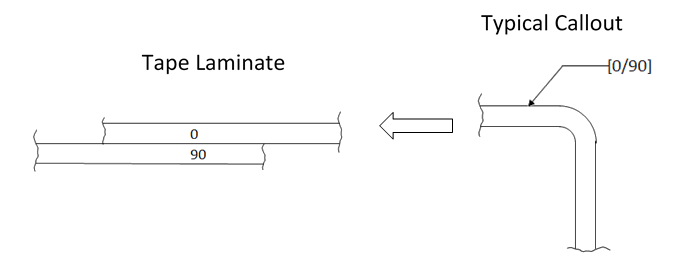
- The lamina/plies are listed in sequence, set off by brackets starting from the side indicated by the code arrow:

- The orientation of the plies is defined relative to the primary load direction of the part. 0o being the primary load direction.
- Adjacent plies with different angles of orientation are separated by a slash.
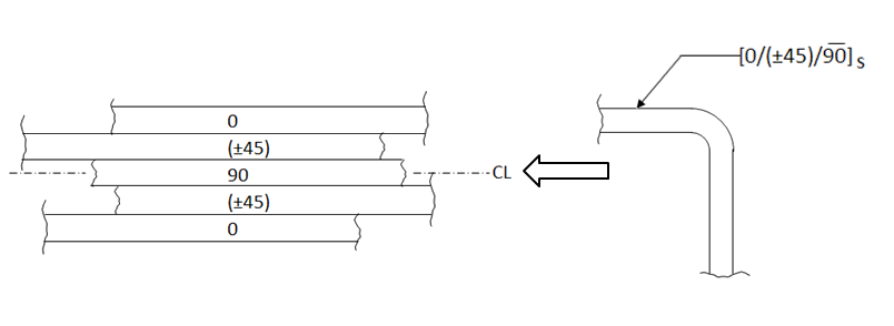
- The callout of fabric plies is differentiated from tape plies by parentheses.
Example: [(±45)/(0,90)]
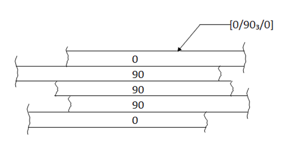
- Adjacent plies of the same angle of orientation are shown by a numerical subscript.
- For tape only when the ± is used two adjacent plies are indicated, with the top symbol being the first of the two:
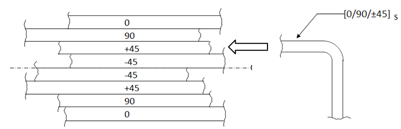
- Symmetric laminates with an odd number of plies have the center one over lined to indicate this condition. Starting with this ply, the rest of the code would be a mirror-image of that part shown.
Note that these forms of laminate definition are not universally used and companies often develop their own simplified versions of these definitions.