This section is taken largely from (![]() MIL-HDBK-17F Vol 3, 2002). Section 9.3 at the back of this reference has some excellent general guidelines for composite laminate design. Where the guidelines are obsolete or incorrect I have not included them. Some guidelines are paraphrased or changed.
MIL-HDBK-17F Vol 3, 2002). Section 9.3 at the back of this reference has some excellent general guidelines for composite laminate design. Where the guidelines are obsolete or incorrect I have not included them. Some guidelines are paraphrased or changed.
4.1.8.1. General Guidelines
- In general, design for large co-cured assemblies. Large assemblies must include consideration for handling and repair.
Lower cost due to reduced part count and assembly time is one of the critical advantages associated with composite aircraft structure. If the assembly requires overly complex tooling the potential cost savings can be negated.
- Structural designs and the associated tooling should be able to accommodate design changes with the inevitable increase in design loads.
- Not all parts are suited to composite construction. Material selection should be based on a thorough analysis that includes consideration of performance, schedule and risk.
- Wherever possible, mating surfaces should be tool surfaces to help maintain dimensional control. If this is not possible precured shims can be used to take up the gap in bonded joints.
- Part thickness tolerance varies directly with part thickness. Thick parts require a larger tolerance.
- Carbon fibers must be isolated from aluminum or steel using a barrier (liquid shim, glass ply, etc).
The galvanic interaction between carbon and certain metals will cause corrosion of the metal component.
- The inspectability of structures must be considered in the design.
- Eliminate or reduce stress risers where possible.
Carbon fiber is linear up to failure and KT’s directly affect static strength.
- Avoid, minimize or mitigate peel stresses within co-cured parts and especially at bonded joints.
- Thin composite laminates can be allowed to buckle with care, but most aircraft projects have a ‘no buckling up to ultimate’ rule. If buckling is allowed before ultimate all secondary load effects must be carefully examined.
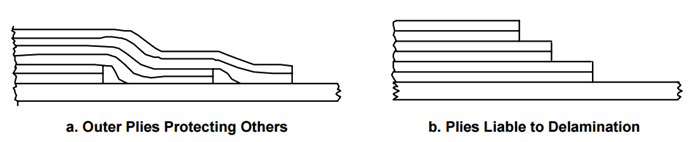
- When adding plies, maintain balance and symmetry. Add between continuous plies in the same direction. Exterior surface plies should be continuous.
This minimizes warping and inter-laminar shear. Continuous surface plies minimize damage to edge of plies and help prevent delamination.
- Never terminate plies in fastener patterns.
It reduces profiling requirements on sub-structure. It prevents delamination caused by hole drilling and improves bearing strength.
- The stacking order of plies should be balanced and symmetrical about the laminate midplane. Any unavoidable asymmetric or unbalanced plies should be placed near the midplane.
It prevents warpage after cure and reduces residual stresses. Eliminates coupling stresses.
- When there are multiple load conditions do not optimize the laminate for only the most severe load case.
- If the structure is mechanically fastened the laminate should be as close as possible to quasi-isotropic.
- Whenever possible, maintain a dispersed stacking sequence. Avoid grouping more than 4 plies of the same orientation together.
It minimizes the tendency to delaminate and creates a more homogenous laminate. It minimizes inter-laminar stresses.
- Locate a ±45 ply at each surface of the laminate.
It minimizes splintering when drilling and protects the plies in the main load carrying direction.
- Avoid abrupt ply terminations. Do not drop more than 2 plies at each termination. Try to drop non-adjacent plies.
Ply drops create stress concentration and load path eccentricities that cause out-of-plane load effects. Thickness transitions can cause wrinkling of fibers and delamination under load. Dropping non-adjacent plies minimizes the joggles of other plies.
- Ply drop-offs should not be less than 20 to 1 in the load direction. i.e. if a single ply is .010 in thick the minimum drop-off spacing should be one ply every 0.2in.
- Skin ply drop-offs should not occur across the width of spars, ribs or frame flanges.
- Ply drop offs should be ‘protected’ by outer plies.
- Butt splice and overlaps: It is common in FAR part 23 aircraft to overlap plies; in part 25 aircraft it is common to butt splice them.
- For part 23 aircraft, different ply overlaps in the same laminate should not be coincident. Ply overlaps should have a minimum spacing of 4 inches and a minimum overlap length of 100 x the ply thickness. Ply overlaps should be avoided where the back side of the laminate interfaces with any other part and should be done away from interfaces with mechanical fasteners.
- For part 25 aircraft, a continuous ply should not be butt spliced transverse to the major load direction and may be butt spliced parallel to the major load direction if coincident plies are separated by at least 4 plies of any orientation. Joints of the plies of the same orientation separated by less than 4 plies of any orientation must be staggered by at least 0.6in. Gaps at butt spliced plies shall not exceed 0.08in.
4.1.8.2. Sandwich Design
- The difference between FAR part 23 and part 25 aircraft core. In general foam core is not used in part 25 primary structures.
- Foam Core: Foam core is commonly used in part 23 aircraft. Foam core is more readily processed, it is easier to machine and can often be used without any additional film adhesive product. Foam core is closed-cell and is generally less prone to moisture absorption than honeycomb core. Foam core also gives more reliable results when used ‘out of autoclave’. Some brittle foam cores have poor damage tolerance characteristics and it is recommended that if possible the softer foam cores are used. Foam cores can also be used with wet laminate composites and also with infused laminates (with some significant weight penalty though). Most foam cores can be thermally pre-formed to gentle compound contours. For large sections of foam core, different foam core panels can be butt joined together with adhesive.
- Honeycomb core creates sandwich panels with superior weight and durability characteristics but is more expensive and more difficult to process. Honeycomb core is more difficult to machine and often requires autoclave processing to give an adequate quality laminate
- Face sheets should be designed to minimize people-induced damage during handling or maintenance of the component.
- Where possible avoid laminate buildup on the core side of the laminate.
- The minimum possible core density should be used to minimize weight. The parameters to consider in selecting core density are as follows:
- Out-of-plane shear strength required for service loads
- Crushing Strength required for service loads
- Crushing strength required to withstand process (autoclave cure)
- A working temperature that can withstand the cure temperature
- Thermal formability (for foam cores)
- Chemical compatibility – Most commercial core materials are formulated for use with epoxy resins, regardless, this should be checked for all materials
- If foam cores have been removed from the packaging or thermally formed some time prior to lamination, foam cores should be ‘baked’ in order to drive any moisture out of the core that may have been absorbed.
- The (
 MIL-HDBK-17F Vol 3, 2002) source material states that core chamfer should be no greater than 20 degrees from the horizontal plane. In practice, 30-degree chamfer angles have been widely used with little or no issues.
 - Fasteners through primary sandwich structure must always be installed using a potted insert. For secondary structure other means such as filler alone can be used.
4.1.8.3. Bolted Joints
- Joint analysis should include the effects of shimming to the level permitted by the drawings.
- Design bolted joint to accommodate the next larger fastener size.
- Maximum Torque values should be controlled – especially with large fastener sizes. This reference (NASA/TM-2006-241323, 2006) shows that fasteners of ¼ diameter and below can be installed using the recommended torque/clamp up without damaging the laminate. These results agree with the author’s experience of test validation on several aircraft programs.
- Bolt bending is much more significant in composites than it is in metals.
- Fastener Shear strength does not usually control the strength of the joint. Carbon fiber laminates have low bearing strengths compared to aluminum.
- Stainless steel fasteners in carbon fiber laminate should be wet installed with a liquid sealing compound.
- Use a layer of fiberglass or liquid shim between aluminum fittings and carbon fiber laminate.
- Countersink depth should not exceed 70% of the laminate thickness.
- Fastener edge distance should be a minimum of 3.0D in the direction of major load, otherwise, 2.5D can be used.
- Use only Titanium, A286, PH13-8 MO, Monel or PH17-4 stainless steel fasteners with carbon fiber/epoxy laminates.
- Do not buck rivets in composite laminate.
- Interference fit fasteners should not be used. Clearance fit should be as tight as possible.
- Tension head fasteners are preferred over shear head fasteners.
- Avoid putting fastener threads in bearings against the laminate
4.1.8.4. Bonded Joints
- The bond should be stronger than the laminate. In shear testing of the laminate and adhesive combination, the failure should occur in the laminate. Reference Section 4.1.3.1 for recommended surface preparation for bonded joints.
- Adhesive bonds should not be used to react either primary peel forces or large induced peel forces.
- The strength of the joint is heavily reliant on surface preparation – mechanical means are best.
- Bonded joints are not critical at room temperature and can be critical at cold dry – not only hot wet. Testing should be performed at all environmental conditions to confirm.
- The edge of the adherends can be tapered/chamfered to reduce peel at the edge of the adhesive joint.
- In general, the thinner the adhesive joint; the higher the strength. Thick laminates and thick adhesive can significantly reduce joint strength.