This method is taken from (![]() AFFDL-TR-69-42, 1986) Section 2.3.2.4.
AFFDL-TR-69-42, 1986) Section 2.3.2.4.
Crippling is a mode of failure that occurs due to compression effects. Typically, this is a check that is applied to thin walled columns where the local stability of the cross section may not allow the column to achieves its full column strength.
The crippling strength of a cross section or feature can be used as a cut off on the column strength curve. See Figure 15.3.5‑1.
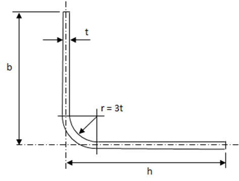
Crippling strength checks are most commonly applied to angles or corner features.
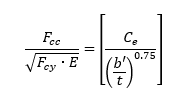
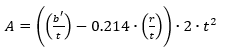
The basic crippling stress equation is:
The Load at which the section above will cripple is given by the following expression:
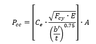
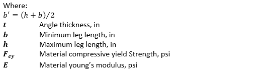
Cross Sectional Area – for the angle shown,
Ce = 0.316 (two edges free)
Ce = 0.342 (one edge free)
Ce = 0.366 (no edge free)
These parameters can be used to construct the curves in the following figure:
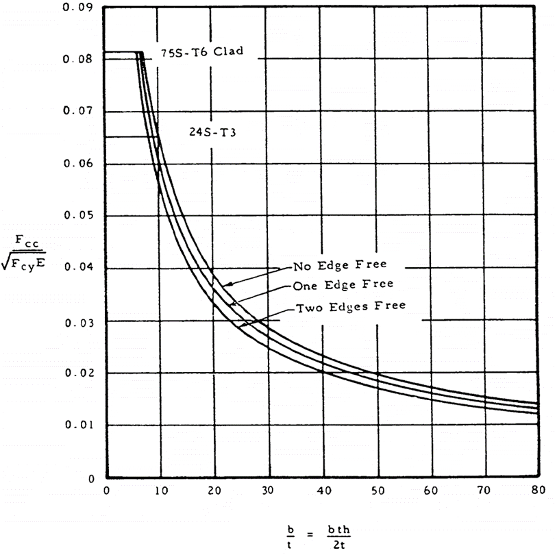
Figure 15.4.1‑2: Dimensionless Crippling Curves (
 AFFDL-TR-69-42, 1986)
 The method is provided in the spreadsheet linked below: