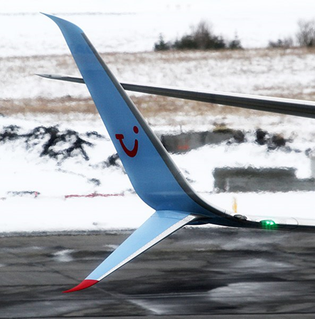
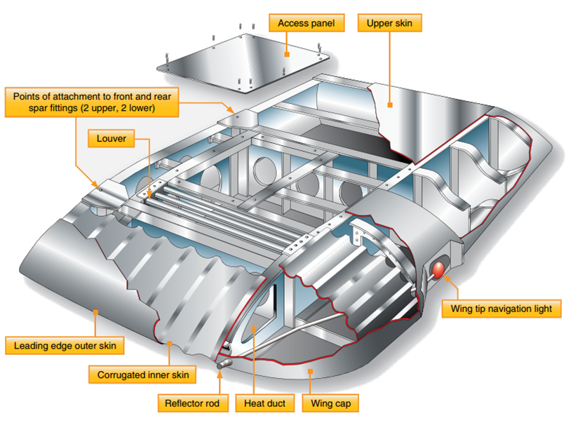
The wing tip is often a removable unit, bolted to the outboard end of the wing panel. One reason for this is the vulnerability of the wing tips to damage, especially during ground handling and taxiing. Figure 1-34 shows a removable wing tip for a large aircraft wing. Others are different. The wing tip assembly is of aluminum alloy construction. The wing tip cap is secured to the tip with countersunk screws and is secured to the interspar structure at four points with ¼-inch diameter bolts. To prevent ice from forming on the leading edge of the wings of large aircraft, hot air from an engine is often channeled through the leading edge from wing root to wing tip. A louver on the top surface of the wingtip allows this warm air to be exhausted overboard. Wing position lights are located at the center of the tip and are not directly visible from the cockpit. As an indication that the wing tip light is operating, some wing tips are equipped with a Lucite rod to transmit the light to the leading edge.
 FAA-H-8083-31, 2012)
 22.16.3.1. Winglet
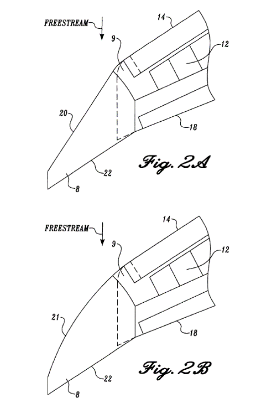
A winglet is an obvious vertical upturn of the wing’s tip resembling a vertical stabilizer. It is an aerodynamic device designed to reduce the drag created by wing tip vortices in flight. Usually made from aluminum or composite materials, winglets can be designed to optimize performance at a desired speed.

There are several variations on the blended winglet that serve the same purpose for drag reduction.