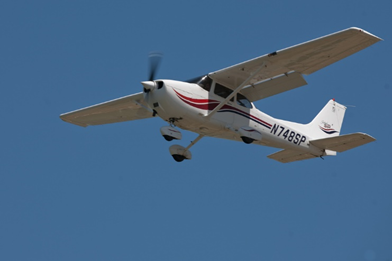
Flaps are found on most aircraft. They are usually inboard on the wings’ trailing edges adjacent to the fuselage. The flaps are lowered to increase the camber of the wings and provide greater lift and control at slow speeds. They enable landing at slower speeds and shorten the amount of runway required for takeoff and landing. The amount that the flaps extend and the angle they form with the wing can be selected from the cockpit. Typically, flaps can extend up to 45–50°. Figure 22.16.4‑1 shows various aircraft with flaps in the extended position.
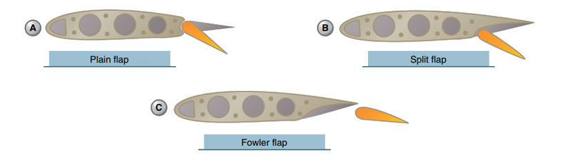
Flaps are usually constructed of materials and with techniques used on the other airfoils and control surfaces of a particular aircraft. Aluminum skin and structure flaps are the norm on light aircraft. Heavy and high-performance aircraft flaps may also be aluminum, but the use of composite structures is also common. There are various kinds of flaps. Plain flaps form the trailing edge of the wing when the flap is in the retracted position. [Figure 1-63A] The airflow over the wing continues over the upper and lower surfaces of the flap, making the trailing edge of the flap essentially the trailing edge of the wing. The plain flap is hinged so that the trailing edge can be lowered. This increases wing camber and provides greater lift. A split flap is normally housed under the trailing edge of the wing. [Figure 1-63B] It is usually just a braced flat metal plate hinged at several places along its leading edge. The upper surface of the wing extends to the trailing edge of the flap. When deployed, the split flap trailing edge lowers away from the trailing edge of the wing. Airflow over the top of the wing remains the same. Airflow under the wing now follows the camber created by the lowered split flap, increasing lift.


Fowler flaps not only lower the trailing edge of the wing when deployed but also slide aft, effectively increasing the area of the wing, reference Figure 22.16.4‑2. This creates more lift via the increased surface area, as well as the wing camber. When stowed, the fowler flap typically retracts up under the wing trailing edge similar to a split flap. The sliding motion of a fowler flap can be accomplished with a worm drive and flap tracks. An enhanced version of the fowler flap is a set of flaps that contains more than one aerodynamic surface. Figure 22.16.4‑3 shows a triple-slotted flap. In this configuration, the flap consists of a fore flap, a mid flap, and an aft flap. When deployed, each flap section slides aft on tracks as it lowers. The flap sections also separate leaving an open slot between the wing and the fore flap, as well as between each of the flap sections. Air from the underside of the wing flows through these slots. The result is that the laminar flow on the upper surfaces is enhanced. The greater camber and effective wing area increase overall lift.
 FAA-H-8083-31, 2012)
 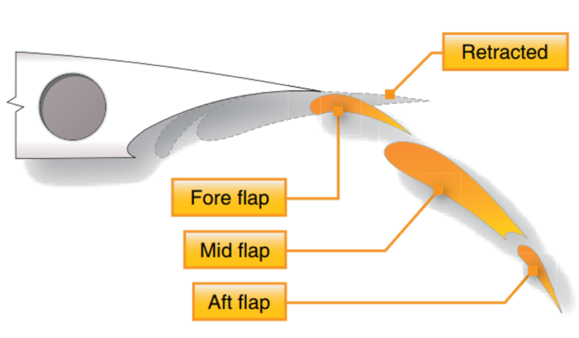 FAA-H-8083-31, 2012)
 The remainder of this section is taken directly from (![]() NASA-CR-4746, 1996). This is an excellent reference written by Peter K. C. Rudolph. This reference contains more useful data than is shown here and the reader is strongly recommended to become familiar with the source material. The text in Italics is taken directly from the source without change.
NASA-CR-4746, 1996). This is an excellent reference written by Peter K. C. Rudolph. This reference contains more useful data than is shown here and the reader is strongly recommended to become familiar with the source material. The text in Italics is taken directly from the source without change.
22.16.4.1. Split Flap
The split flap was widely used in earlier days, especially on military airplanes. It is a good attitude and glideslope control device, but it does not produce much lift increase. However, as a speed brake it is better than a spoiler because it produces drag without losing lift. The split flap is not used on any modern airliner. It is used on low performance part 23 aircraft.
 NASA-CR-4746, 1996)
 22.16.4.2. Plain Flap
The plain flap has a panel with a rounded upper leading edge that deploys by downward rotation without opening a slot. The deployment angle is limited to about 20°; beyond that, the flow separates on the upper surface. Because this restriction limits its lift-producing capability, it is not used on any modern airliner. However, it has come in through the back door—any inboard or outboard aileron that is drooped at low speed (flaperon) is a plain flap.
 NASA-CR-4746, 1996)
 22.16.4.3. Simple Slotted Flap
The simple slotted flap has a flap panel with a fully developed aerodynamic leading edge. It is generally mounted on pivots a little below the lower wing surface and is deployed into a slotted down position of 30° to 35°. The simple slotted flap has very little flap overlap with the fixed trailing edge and hence develops only little Fowler motion, defined as aft travel of the flap that increases wing area.
Also, the flap motion does not move far enough away from the lower cove panel to develop a good entry into a slot. Therefore, it requires a rounded cavity on the lower surface, which is a solution suitable only for low—speed airplanes. For high-speed airplanes, the lower cove panel has to be rotated upward with a slave linkage, so the simple flap turns out to be not quite that simple. The simple slotted flap is not used on any modern airliner as a main flap concept, but the concept is used for flaperons.
 NASA-CR-4746, 1996)
 22.16.4.4. Single Slotted Fowler Flap
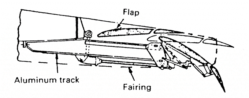
When stowed, Fowler flaps have significant overlap between flap and spoilers or the fixed upper cove panel. In the fully deployed position, this overlap is converted into Fowler motion by moving the flap aft, which effectively increases wing area. The single-slotted flap is the simplest of all Fowler flaps and therefore the most attractive one from a weight and cost point of view. With careful aerodynamic design, a single-slotted flap can be deflected to about 40°.
Single-slotted flaps were widely used in the early days of the jet age, then they were displaced by more sophisticated double- and triple-slotted flaps, and now they are making a comeback.
 NASA-CR-4746, 1996)
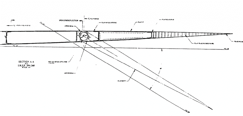
 22.16.4.5. Fixed Vane/Main Double Slotted Flap
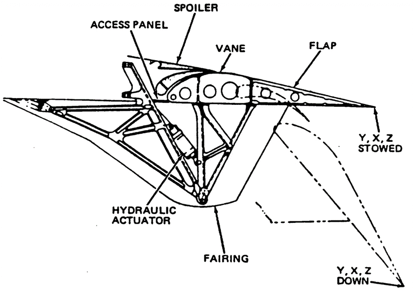
The fixed vane/main flap has a vane rigidly attached to the main flap, which forms a fixed—geometry slot. When fully deployed, the flap is double-slotted and allows flap deflections of as much as 55°.
The vane in its stowed position is trapped between the spoiler above and a lower cove panel. Extracting the vane out of this slot imposes restrictions on the mechanism design. The fixed vane/main flap is only slightly heavier and costlier than the single- slotted flap, it produces a little more lift, and it helps adjust airplane attitude on landing approach.
For takeoff, it is generally desirable to have the vane sealed against the upper cove panel or spoilers because in this setup only the second slot is open and takeoff L/D is improved. However, with complex vane extraction from the cove and a second geometric constraint of providing a single- slotted takeoff position, very few mechanisms qualify for the fixed vane/main flap. Nonetheless, the fixed vane/main flap is used on many commercial airliners.
 NASA-CR-4746, 1996)
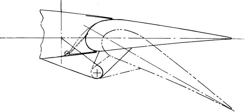
 22.16.4.6. Articulating Vane/Main Double Slotted Flap
Making the vane retractable relative to the main flap creates a second overlap that can be used to increase both Fowler motion and the total developed wing chord relative to a fixed vane/main flap.
This step is accomplished with no change in the occupying space in the wing. However, the articulating vane/main flap adds quite a bit of complexity to the design.
Generally, vanes are not actively actuated but are spring-loaded into the deployed position and stowed by the stow stop and the actuating force of the main flap. The structural-vane-to-main—flap connections are generally either straight or circular arc tracks that penetrate the front spar of the main flap. If an active mechanism for moving the vane relative to the main flap is used, it is easier to provide a single-slotted takeoff position with the slot in front of the vane and the vane-to—main—flap slot closed.
However, this configuration reduces Fowler motion available for takeoff and increases complexity.
Both fixed and articulating vane/main flaps need “smart” mechanisms to take full advantage of their aerodynamic capabilities. The challenge is not only to extract the vane from the cove without slave linkages, but to keep the vane in contact with the upper-cove trailing edge (spoilers) during initial deployment for flap angles of 5° to 15° so that the flap stays single-slotted for typical takeoff settings for best takeoff L/D.
 NASA-CR-4746, 1996)
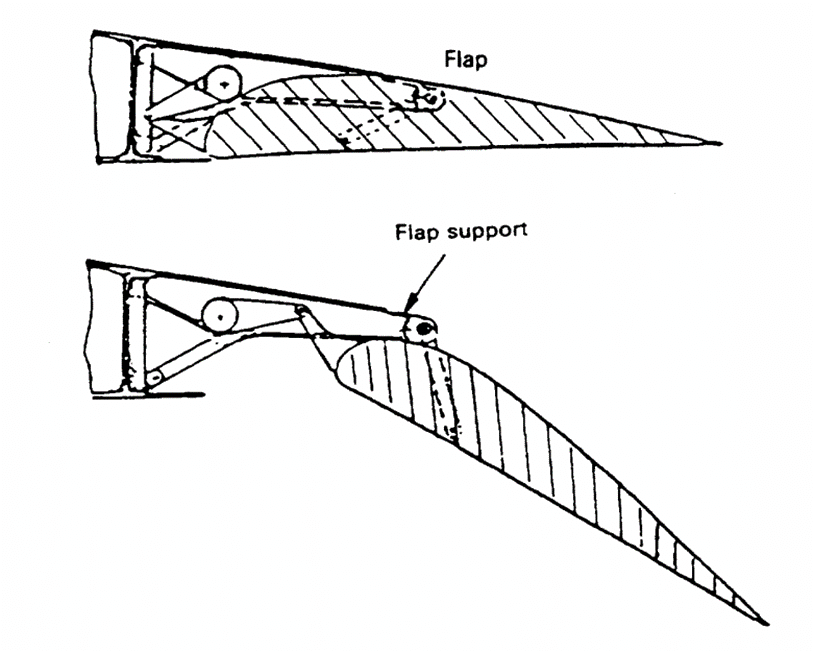
 22.16.4.7. Main/Aft Double Slotted Flap
Main/aft double-slotted flap— The main/aft double-slotted flap is one step farther in complexity beyond the articulating vane/main flap. The forward or main flap is the larger element and the aft flap the smaller, and the main flap has its overlap with the wing cove while the aft flap overlaps with the aft end of the main flap. Typical flap deflection angles are 30° to 35° for the main flap and 28°
to 30° for the aft flap, for a total deflection of 60° to 65°. A main/aft flap generally achieves more Fowler motion than an articulating vane/main flap with the same stowed chord length. Thus, it produces slightly more lift and helps adjust airplane landing attitude.
 NASA-CR-4746, 1996)
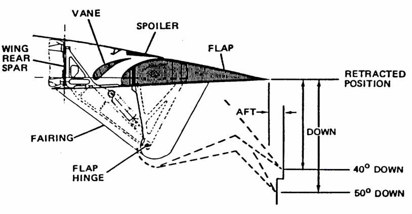
 22.16.4.8. Triple Slotted Flap
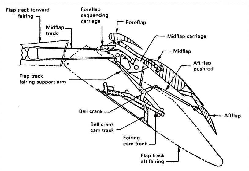
A triple-slotted flap is like an articulating vane/main flap with an additional aft flap added to the main flap. Since it has three overlaps, it can provide very high Fowler motion, and the three slots allow deflections of the aft flap to as much as 80°.
Because all three of the flap elements have to be supported structurally and their motion somehow geared together, the triple- slotted flap is very complex and heavy. It produces higher sectional lift than the double-slotted flap, but edge losses are very significant (one vortex per flap panel edge). The nose-down pitching moments are very high and need to be trimmed by a tail-down load, which further reduces its benefits. Three Boeing airplanes use triple-slotted flaps—the 727, 737, and 747.
 NASA-CR-4746, 1996)