Leading edge devices can be split into the following types:
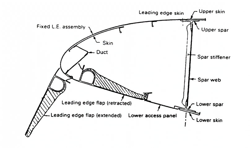
22.16.5.1. Hinged Leading Edge (Droop Nose)
Hinged leading edge (droop nose)— There is no known use of a hinged leading edge on a commercial subsonic airliner. Droop—nose leading edges have been used on some fighter airplanes.
The major drawback of the hinged leading edge is that the radius of curvature on the upper wing surface is too tight and causes flow separation. Flow separation is not a problem on a supersonic airplane, where a much higher leading-edge sweep angle triggers a stable vortex on the upper surface, which provides lift.
 NASA-CR-4746, 1996)
 22.16.5.2. Variable Camber (VC) Leading Edge
A VC leading edge was successfully tested on NASA’s Advanced Flight Technology Integration (AFT I) 111 experimental airplane. However, because low-speed,high-lift characteristics are not good, it is not in use on subsonic commercial airliners.
 NASA-CR-4746, 1996)
 22.16.5.3. Fixed Slot
The fixed slot has been used successfully on short takeoff and landing (STOL) airplanes with slow cruise speeds. The drag penalty of fixed slots is unacceptable for a high- performance subsonic airliner.
 NASA-CR-4746, 1996)
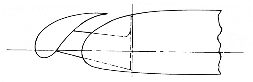
 22.16.5.4. Simple Krueger Flap
The simple Krueger flap consists of a panel on the lower side of the wing leading edge. A hinge on the forward end of the panel allows it to rotate first downward and then forward into a position where its forward edge seals against the lower surface of the fixed—wing leading edge. The panel is at an angle of 60° to 80° relative to a horizontal line. The simple Krueger flap is used on the inboard wing of the Boeing 707.
The Krueger flap is the simplest leading-edge device in use on high—performance airliners. Its high—lift performance is adequate for inboard wing sections, but its deficiency lies in its inability to accommodate varying angles of attack. During normal operation, there is generally a stagnation bubble on the upper aft portion of the Krueger panel.
 NASA-CR-4746, 1996)
 22.16.5.5. Folding, Bull-Nose (Rigid), Krueger Flap
The simple Krueger flap can be improved by adding a folding bull nose to it. Hinged to the aft end in the stowed position, the folding bull nose is a panel that runs the length of the main Krueger panel. It has a D-shaped cross section, and it is connected with a slave linkage that rotates to deploy the bull nose as the main Krueger panel deploys. Because of the rounded bull nose, the folding, bull-nose Krueger is more tolerant to changes in angle of attack. As a result, the flow on the upper surface of the Krueger is attached over a wider angle-of—attack range.
The folding, bull-nose Krueger has generally been used without a slot betweenthe Krueger and a fixed-wing leading edge. The simple Krueger flap and the folding, bull-nose Krueger flap are generally used as two position devices with the deployed position biased toward an optimum landing configuration (CLmax)- A third position that is more optimum for takeoff is possible, but it requires a more complex mechanism or fairing concept.
 NASA-CR-4746, 1996)
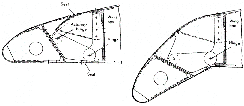
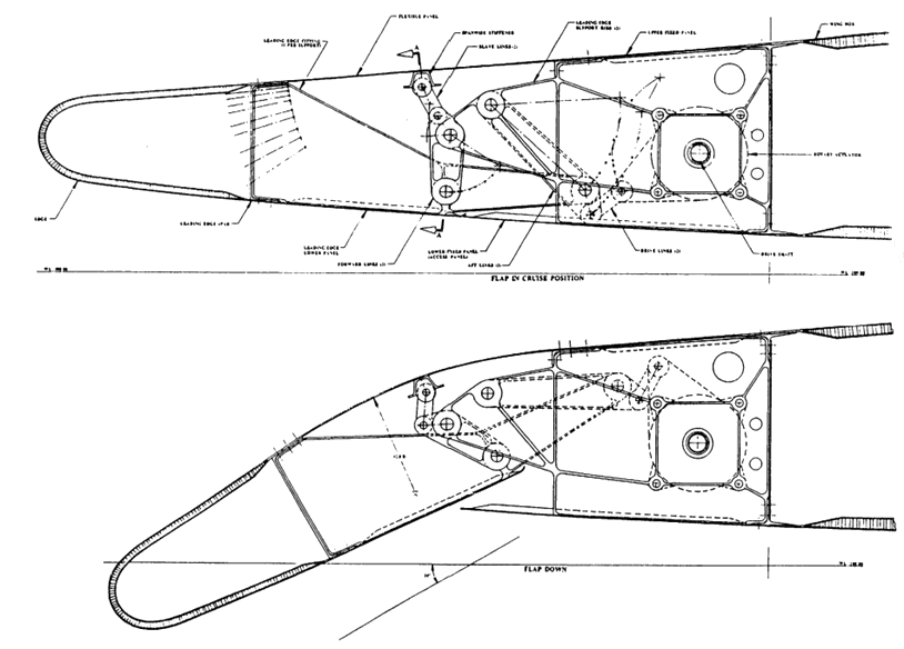
 22.16.5.6. Variable Camber Krueger Flap
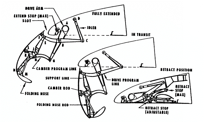
Figure 22.16.5‑6 shows the VC Krueger flap, one attempt to improve the shape of the
deployed Krueger flap. The shapes of the simple Krueger flap and the main panel of the folding, bull—nose Krueger flap are dictated by the airfoil shape at the lower surface of the wing leading edge.
The VC Krueger changes the main Krueger panel from a rigid to a flexible panel, which improves the airfoil shape of the Krueger dramatically and also improves the aerodynamic performance of the Krueger.
This improvement, however, comes with a penalty. The linkage for the VC Krueger is a more complex 4-bar linkage, and the main Krueger panel has to be flexible in a line normal to the wing leading edge. This flexibility is accomplished with a fiberglass panel and only two stiffeners in the form of hat sections parallel to the leading edge.
As a result, the bending stiffness of this panel in the spanwise direction is limited. Whereas a rigid Krueger panel with two spanwise hinges can be designed for a span equivalent to the span of a slat (100 to 150 inches, depending on the size of the airplane), the practical span of a VC Krueger panel is limited to about half that. Therefore, about twice as many spanwise panels are needed for a VG Krueger as compared to a rigid Krueger or a slat, thus making the VC Krueger a complicated and expensive device. Rigging problems associated with the flexible panels are also present because the flexible panels tend to distort under high cruise air loads. A careful preloading of the flexible panels is required to avoid panel bulging with panel mismatch, which could cause cruise drag penalties.
 NASA-CR-4746, 1996)
 So far, the VC Krueger flap has been exercised only as a two-position device with the deployed position biased toward an optimum landing configuration. Therefore, the takeoff lift/drag ratio (LID) is not good. Attempts to make the VC Krueger a three-position device have not been successful.
22.16.5.7. Two Position Slat
two—position slat was the Handley Page slat, which was mounted on curved tracks, deployed with the help of aerodynamic forces, and stowed with the force of a preloaded spring. This design was also used on the F-84 fighter aircraft. No two-position slats are known to be in use on commercial airliners.
 NASA-CR-4746, 1996)