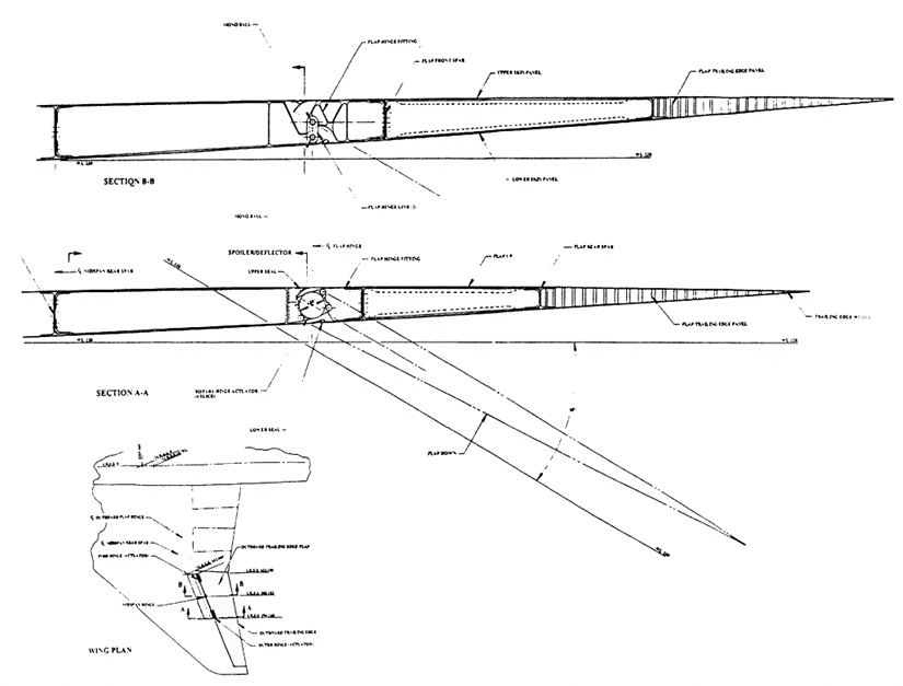
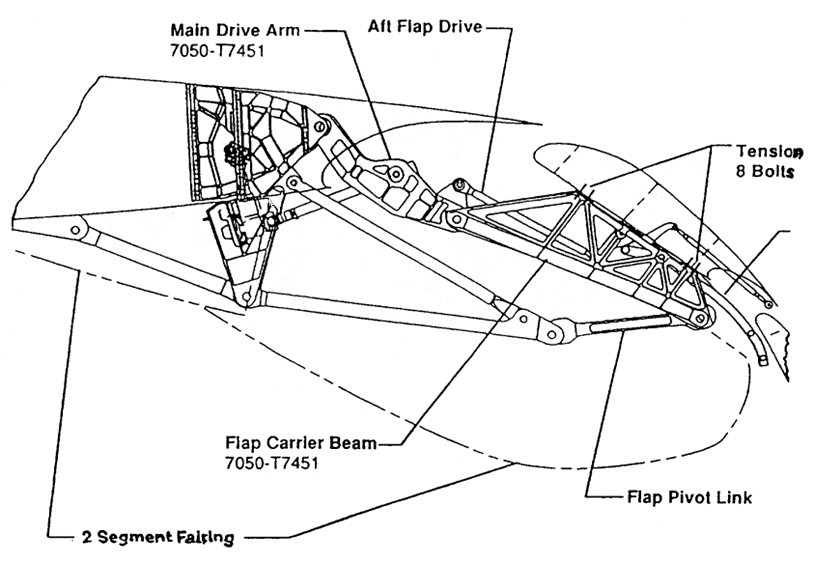
The basic elements to guide and structurally support a moving element such as a flap or a slat panel are hinges, linkages, and tracks. Each panel is generally supported in two spanwise locations with two fixities in each location. Since a statically determinate system needs only three support points, the fourth support point is redundant and creates a potential for force fight. The best spanwise support location is generally at a point about 25 percent of the distance from the ends of a panel, but buried support systems sometimes require supports at the end of the panel. Also, the large spanwise dimension of an outboard flap panel and its limited thickness may require a third support location to avoid making two outboard flaps. The third support location has to be designed to avoid a force fight between flap and wing. Figure 22.16.6‑1 shows a simple example of such an arrangement for the thin flap panel of a supersonic airplane. A panel with three hinges has two rigid hinges, with the third hinge on a swing link. As the wing box (the stronger and stiffer element) bends under a flight load, the three hinge points go out of alignment, and the swing link of the third hinge can rotate. This process still forces some bending into the flap panel, but the high-stress shear loads in the flap plane are avoided.
Actuation of high—lift devices can be done either individually for each support or panel, or it can be geared together with drive shafts powered by a centrally located power drive unit (PDU). For an individual drive, the hydraulic actuator is the most commonly used drive unit. If more than one actuator is used per panel, the panel has to become the synchronizing torque member in case of an actuator force fight due to actuator failure. This situation explains why multiple linear hydraulic actuators are found only on hinged panels or circular arc tracks where the panel can transmit torque. On flap mechanisms that provide good initial Fowler motion (translation), multiple linear actuators cannot be used because the panel translation cannot transmit torque.
 NASA-CR-4746, 1996)
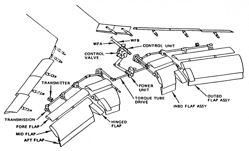
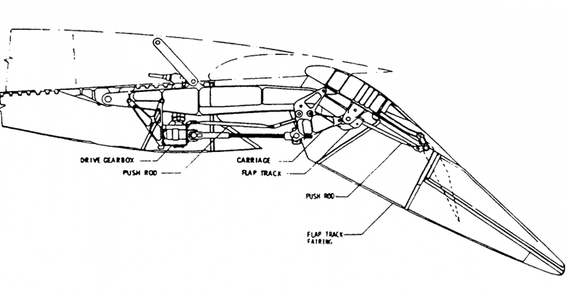
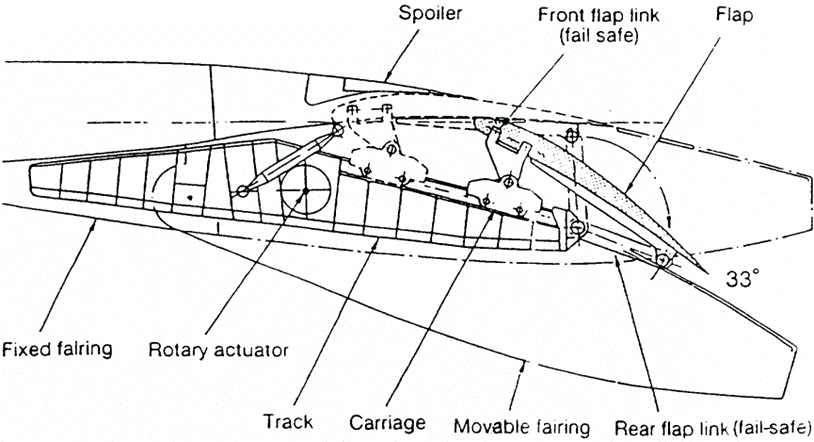
 Centrally powered and synchronized actuation systems use screw jacks, rotary hinges, rotary actuators, or rack and pinion drives as actuators. This drive system has become the one most frequently used for trailing-edge and leading-edge flaps because it is the surest and safest way to synchronize flap deployment. Figure 22.16.6‑2 shows the Boeing 737 trailing-edge-flap drive system.
A drive system of this nature has been used on the trailing-edge flaps of all Boeing airplanes since the 707 and on all Airbus airplanes. A similar drive system has been used for leading-edge actuation on all Boeing airplanes beginning with the 747 and on all Airbus airplanes. In addition to the synchronizing nature of the shafts, the high reduction ratios of the gearboxes make the system essentially self-locking. Shafting is generally designed to withstand jam failures. Therefore, additional brakes or no—backs and symmetry-sensing devices are redundant safety features. In other words, this actuation system is the safest one against asymmetric and passive failures. Dual motorson PDUs guarantee functional reliability on demand.
 NASA-CR-4746, 1996)
 22.16.6.1. Trailing Edge Devices
Numerous support mechanisms are known for trailing-edge flaps, and new ones are being invented and reinvented all the time. Leaving out hinges and actuation systems for flaperons and simple flaps for supersonic airplanes, the emphasis here will be on conventional trailing—edge flap mechanisms.
Definition of Fowler Motion
Before describing trailing-edge flap mechanisms and their relative benefits, it is first appropriate to define one of the major goodness factors, namely Fowler motion. It is not clear how Mr. Fowler defined his motion. Most aerodynamicists today see the significant parameter to be the increase in developed wing chord, which means chord in space and not just the wing chord projected into the wing reference plane as shown in several publications. Using just projected chord change makes the Fowler motion of many flaps negative because the rotation shortens the projected flap chord. So, for this report, Fowler motion is defined as the incremental, developed chord measured in the wing chord plane for slats.
 NACA-TN-578, 1936)
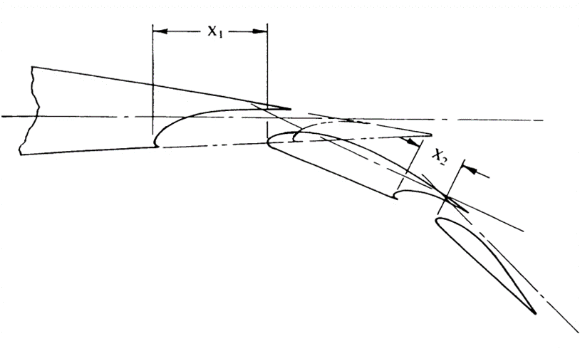
 For trailing—edge flaps with multiple elements, Fowler motion is measured in linear increments in the chord plane of the respective upstream element, as shown in Figure 22.16.6‑4. Measuring the Fowler motion in linear increments in chord planes is a practical approximation to the real chord extension as measured in a curve on the upper surface of the elements. The Fowler motion for landing, with the flaps in the fully deployed position, is independent of flap linkage, and therefore it is a function only of the flap overlap provided.
 NASA-CR-4746, 1996)
 A “smart” flap mechanism provides most of the available Fowler motion in the initial flap deployment at low deflection angles. This area increase at low-flap-angle settings results in the best MD for takeoff.
Simple Hinge for Fowler Flap
Good performance for a hinged, overlapping flap requires a flap pivot far below the wing surface whether it is a single, vane/main, or main/aft double-slotted flap.
The words “simple pivot” used for this arrangement are not accurate; this concept requires a pivot far away from the wing box and requires a fairly deep, fixed hinge fitting. The flap hinge fitting is about the same size, and both fittings are encased in large, flat-sided fairings. (See Figure 22.16.4‑9) The long and narrow hinge fittings cannot transmit the flap side loads, so another side-load reaction has to be provided, either in the form of A-frame-type links or a side-load track. The circular arc motion of a hinged flap develops Fowler motion proportional to the deployment angle. For low deployment angles required for high-gross—weight takeoff, the hinged flap develops little Fowler motion, and it is therefore not the best mechanism for this requirement. The simple hinge is an example of a “dumb”mechanism.
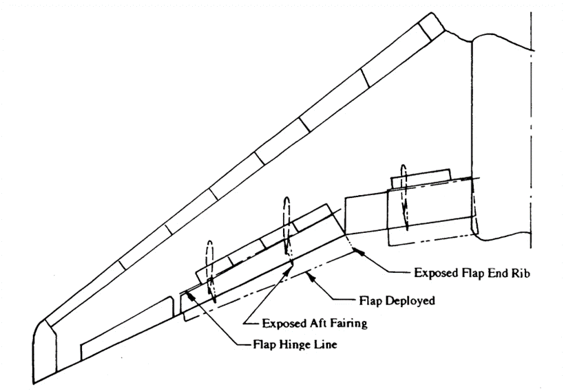
Yet another bad feature is associated with simple hinges. Hinged flaps are not easily adaptable to streamwise motion on swept, outboard wing trailing edges. The swept hinge axis of the simple hinge flap rotates the aft hinge fairing into a skewed angle inboard and out of the wake of the forward fixed fairing, which produces drag. Also, the inboard end of an outboard flap is not trimmed.
in a streamwise direction, so the skewed end rib is exposed to full ram pressure when the flap is deployed, producing still more drag (See Figure 22.16.6‑5). This same characteristic makes sealing a swept, outboard flap against an unswept, inboard flap difficult.
Upright, Four Bar Linkage
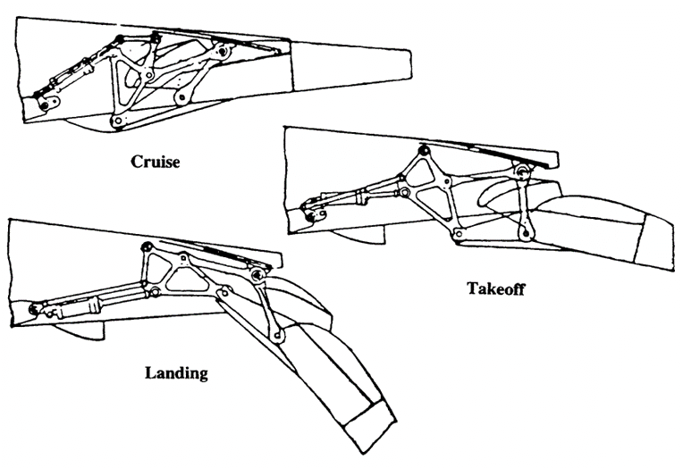
The four—bar linkage with upright links reduces the fairing depth by 30 to 35 percent as compared to a simple hinge and improves the Fowler motion schedule.
Figure 1.25 shows such a linkage exercised in three variations for a main/aft double-slotted flap. The results are somewhat better than those produced by a simple-hinge, double-slotted flap as used on the Boeing YC-14.
 NASA-CR-4746, 1996)
 Upside-Down, Four-Bar Linkage
The upside-down, four-bar linkage has a much better potential for applications to trailing-edge flaps. The two links at any support location are hinged on a fixed structure at their upper end and to the flap or a flap carriage at their lower end. When used as an end support, the links can be buried completely inside an airfoil, with no need for flap support fairings.
This configuration, of course, means lower drag at both low and high speeds. For example, refer to the Boeing 747SP flap shown in Figure 22.16.4‑7.
The upside-down linkage in its more compact form (shortest links) tends to drop the flap down and create some counterrotation during the initial part of deployment. It is therefore not advantageous for a vane/main flap that needs to extract the vane from the slot between the upper and lower cove unless the vane is made small and with little overlap, which is the case on the Douglas DC-8 (Figure 22.16.6‑7). However, the DC-8 flap mechanism is not a plain four-bar linkage, but rather has the upper pivot of the aft link move aft in a short, straight track. This motion is slave-linked to the forward link. The upside—down, four-bar linkage is good for a single-slotted flap and for the main and aft flaps of a main/aft type double—slotted flap. McDonnell Douglas used this concept again on the YC-lS and the 017 for blown, double-slotted, main/aft-type flaps (Figure 22.16.6‑8).
 NASA-CR-4746, 1996)
  NASA-CR-4746, 1996)
 The Fowler motion progression of the upside-down, four-bar linkage is quite good, achieving high Fowler motion at small flap deployment angles for good takeoff L/D. It is not clear who invented this linkage or used it first on a trailing—edge flap, but it has repeatedly been claimed as a novel linkage. The linkage can be adapted for streamwise conical motion, which is required to allow inboard and outboard flaps to seal against each other. Actuation power requirements can become quite high.
Upside-down/upright four-bar linkage
Of the two combinations possible within this concept, the arrangement with the upside-down link forward and the upright link aft seems to have the most promise. Whether this concept is better or worse than the pure upside-down linkage is not clear, but at first glance it looks about as good as the other concept. It can be easily adapted to conical, streamwise motion. The fairing size required to house the linkage is fairly deep, but short. Actuation power requirements are, as on the upside-down concept, fairly high. The upside—down/upright, four-bar
linkage is used on the Boeing 777 inboard main flap and single-slotted outboard flap (Figure 22.16.6‑9).
 NASA-CR-4746, 1996)
 Complex four-bar linkages
Many recent attempts have been made to design more complex linkages for trailing-edge flaps. The design goal of most of these attempts has been to squeeze another percent or two of additional Fowler motion out of the concept for low-takeoff flap angles.
One of the more memorable attempts was called a “walking beam four-bar linkage,” where a beam located underneath the flap is moved aft with an upside-down linkage while the flap is moved aft and rotated with an upright, four-bar linkage that rides on the “walking beam.” The concept, of course, needs more slave links, and for fail-safety, every link is duplicated. The same linkage is then repeated for the aft flap with more slave links, and, as a result, the number of links and pivot points is about 20 per support location, which makes the concept very expensive to build and maintain. The major flaw of this kind of approach is that there are too many joints in series, which increases both the probability of failure and the chance that joint wear will result in a wiggly support.
One successful implementation of a complex linkage flap support, best described as a hinged-beam/upside—down/upright, four-bar linkage (Figure 22.16.6‑10), is used on the Boeing 767 for the main flap panel of the inboard flap and the single-slotted outboard flap. The flap is mounted on an upside-down/upright, four-bar linkage with the forward, upside-down link hinged on a fixed structure and the upright, aft link hinged on the folding beam. The folding beam itself is hinged on a fitting on the lower surface of the wing box. As the four-bar linkage moves the flap aft and rotates it into the landing position, the hinged beam first moves down and then up.
 NASA-CR-4746, 1996)
 This process negates some of the up—and-down motion of the aft link to avoid flap interference with the spoiler and to create proper flap gaps. The concept is ingenious because it creates a lot of Fowler motion at low flap angles. However, it has some of the flaws discussed earlier: The multiple links and joints in series require doubling of most links for fail-safety. This configuration adds to the complexity and cost of the design and makes it difficult, if not impossible, to accomplish streamwise deployment of the flaps. Therefore, the disadvantages of the simple hinge flap apply to the 767 linkage—a slanted end trim of the inboard end of the outboard flap that does not allow sealing with the inboard flap, and rotation of the slanted inboard-flap end rib and aft-flap fairing into the free stream. In addition, the duplicated linkage is wide and essentially normal to the rear spar. Hiding this normal linkage in a streamwise fairing makes for a wide fairing with a lot of slot blockage and reduced flap performance.
Hooked-track supports
Before discussing hooked-track supports, a discussion about the Boeing 707 circular—arc—flap support track is in order. This track is located forward of the flap inside the airfoil. It does not provide any fancy motion but deploys the flap from stowed to full extension. This mechanism is light and does not require any flap fairings. Details about this flap mechanism can be found in Chapter 2.
Hooked tracks used to deploy the main flaps of successive Boeing airplanes (727, 737, 747, and 757, Figure 22.16.6‑11) have been quite successful. The forward end of this hooked track is essentially straight and slopes downward; therefore, initial flap motion is aft and slightly down. A good portion of Fowler motion can thus be obtained at low flap angles for takeoff. The aft end of the track is hooked down and accomplishes the major part of the flap rotation for the landing configuration. The hooked-track concept lends itself to conical streamwise flap deployment, which allows a sealed interface between a straight-motion, unswept, inboard flap and a conical-motion, swept, outboard flap.
The major drawback of the hooked-track concept is that the reaction to the flap air loads, which are generally aft of the carriage, results in a couple between the front and aft rollers of the roller carriage. For practical purposes, this couple is not very long, and the result is very high aft roller loads. Therefore, designing rollers and tracks for reasonable service life is not easy.
It is not clear who invented the hooked-track flap support. In addition to the use on four Boeing airplane models, it is used by British Aerospace on the BAe146 and RJ70/ 100/ 120 airplanes and by Airbus on the A310 airplanes.
 NASA-CR-4746, 1996)
 Link/track mechanisms
Most of the linkage systems described in the previous paragraphs have the problem that one link wants to be quite long for ideal flap motion and does not fit into the minimum fairing envelope. It should be recognized that an infinitely long link can be simulated with a straight track. This thought process led to the evolution of several link track mechanisms. For the link/track flap mechanism, the low overturning moment from the flap loads creates a couple between the roller carriage and the front link or aft link and drive rod. This setup reduces roller loads and provides good roller/track wear characteristics. The advantages of this arrangement were recognized at Boeing in the late 19705, but it was not vigorously pursued. Airbus is using two of these concepts on the Airbus A320/321 and A330/340 airplanes.
Airbus A320 flaps use an upside—down, forward link in conjunction with a straight track on a fixed structure as aft support (Figure 22.16.6‑12). The motion of this mechanism is very favorable for Fowler motion at lower takeoff flap angles and requires very low actuation power. In addition, the mechanism is adaptable to streamwise conical motion.
 NASA-CR-4746, 1996)
 The A330/340 flap mechanism uses similar elements, but in a different arrangement; it has a straight and sloped track on fixed structure as forward support and an upright link as aft support (Figure 22.16.6‑13). Again, Fowler motion progression is very good, but no better than on the A320.
 NASA-CR-4746, 1996)
 22.16.6.2. Leading Edge Devices
Slats
As mentioned earlier, most slats in service on commercial airliners are mounted on circular arc tracks with two tracks per slat panel. The tracks generally have an I—beam cross section. In the Boeing version, the rollers are engaged with the outside flanges of the I-beam, they are end- supported, and each roller reacts against either a down or an up load. Some Airbus airplanes use larger, cantilevered rollers that roll inside the flanges of the I—beam and react against both up and down loads. The air loads on a slat are essentially normal to the path of deployment by the circular arc tracks. Therefore, the magnitude of the actuation loads is low. Slats see air-load reversal at low angles of attack, generally on the ground.
Several different actuator arrangements for slat actuation are used on today’s commercial airliners. The biggest number of in-service airliners, the Boeing 727 and 737 airplanes, use a single hydraulic actuator to deploy each slat. Today’s design standards indicate that the single actuator is not sufficient, and two actuators are required to avoid racking of the slat panel in the tracks. However, practical experience indicates otherwise: none of the approximately 4500 Boeing 727 and 737 airplanes in service today have slat deployment problems. The slats have a programmed deployment/stow schedule that makes them deploy at different times, and symmetry is maintained with the help of electrical position signaling.
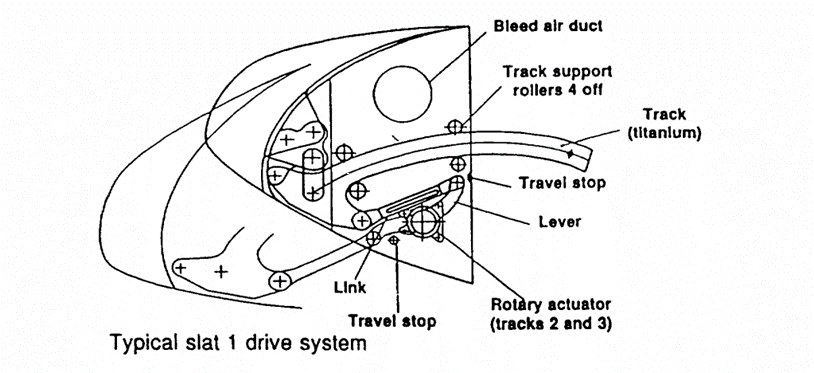
Other slat-actuation schemes use rotary actuators with drive links, as on the Boeing 767 and on the inboard slats of several other airplanes, including the Airbus A340. (Figure 22.16.6‑14).
Screw jack drives are suitable as well to actuate slats; they are used on the Airbus A300 and A310 airplanes (Figure 22.16.6‑15).
 NASA-CR-4746, 1996)
 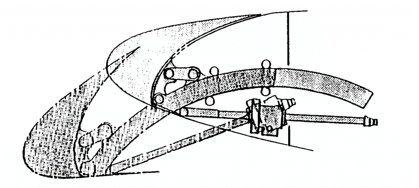 NASA-CR-4746, 1996)
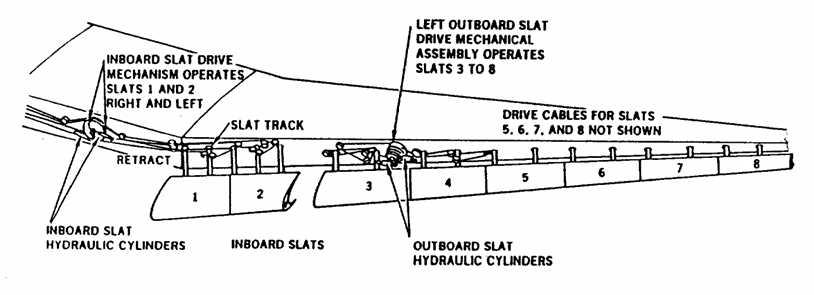
 McDonnell Douglas and Fokker use cables to actuate slats. The slats have a conical motion, so travel at every track location is different. This configuration is accomplished using cables wrapped around drums with different diameters to achieve different lengths of travel. However, this system has many flaws: the difficulties of rigging the cables and maintaining preload in the system; the large number of pulleys; and a concern for safety since this drive system has no sure way to lock the slats in place in case of actuator failure. A Douglas DC-lO/MD-ll slat-actuation system is shown in Figure 22.16.6‑16.
 NASA-CR-4746, 1996)
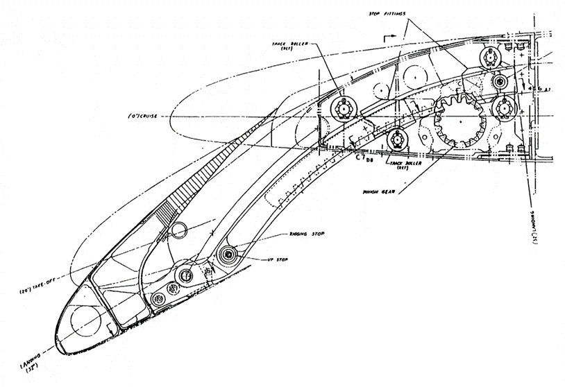
 Lately, the rack and pinion drive (Figure 22.16.6‑17) has become the most popular drive system for slats. First used on the Boeing 757 airplane, it has been copied by the Airbus A320/321, the A330/340, and the Boeing 777 airplanes. This drive uses a rotary hinge that has an outer rotating case and is configured as a spur gear to drive a rack. This rack is a structural part of the circular arc track, and power comes from a centrally located PDU that also synchronizes the system between right- and left-hand sides of the airplane.
 NASA-CR-4746, 1996)