The wings of an aircraft are designed to lift it into the air and they carry the weight of the aircraft. The wing design for any given aircraft depends on a number of factors, such as size, weight, use of the aircraft, desired speed in flight and at landing, and desired rate of climb. The wings of aircraft are designated left and right, corresponding to the left and right sides of the operator when seated in the cockpit.
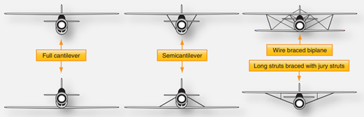
Often wings are of full cantilever design. This means they are built so that no external bracing is needed. They are supported internally by structural members (spars and ribs) assisted by the skin of the aircraft. Other aircraft wings use external struts or wires to assist in supporting the wing and carrying the aerodynamic and landing loads. Wing support cables and struts are generally made from steel. Many struts and their attach fittings have fairings to reduce drag. Short, nearly vertical supports called jury struts are found on struts that attach to the wings a great distance from the fuselage. This serves to subdue strut movement and oscillation caused by the air flowing around the strut in flight.
Figure 22.16.2‑1 shows samples of wings using external bracing, also known as semi cantilever wings. Cantilever wings built with no external bracing are also shown.
Aluminum is the most common material from which to construct wings, but they can be wood covered with fabric, and occasionally magnesium alloys have been used.
Modern aircraft tend towards lighter and stronger materials throughout the airframe and in wing construction. Wings made entirely of carbon fiber or other composite materials exist, as well as wings made of a combination of materials for maximum strength to weight performance.
 FAA-H-8083-31, 2012)
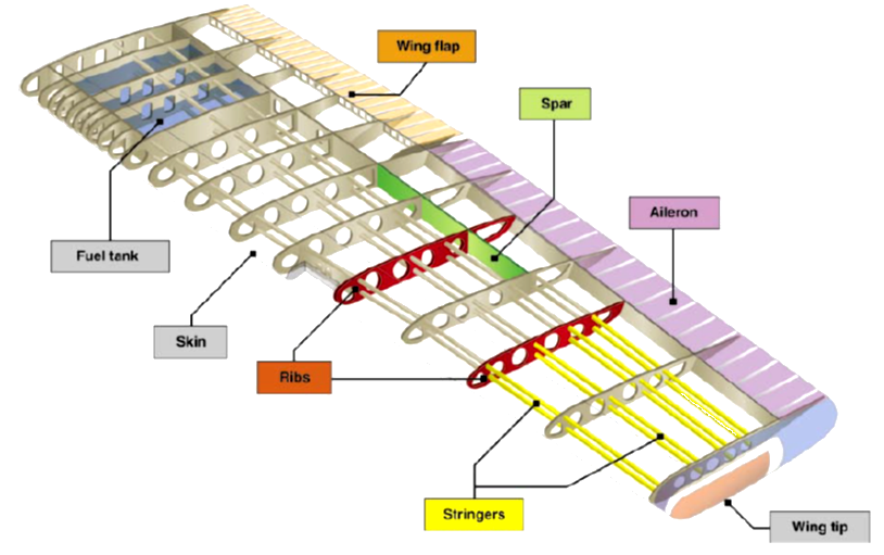
 The internal structures of most wings are made up of spars and stringers running spanwise and ribs and formers or bulkheads running chordwise (leading edge to trailing edge). The spars are the principle structural members of a wing. They support all distributed loads, as well as concentrated weights such as the fuselage, landing gear, and engines.
 FAA-H-8083-25A, 2008)
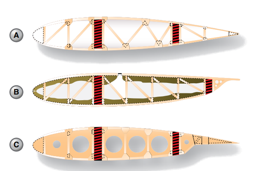
 The skin, which is attached to the wing structure, carries part of the loads imposed during flight. It also transfers loads to the wing ribs. The ribs, in turn, transfer the loads to the wing spars. Figure 22.16.2‑4 In general, wing construction is based on one of three fundamental designs:
1. Mono-spar
2. Multi-spar
3. Box beam
Modification of these basic designs may be adopted by various manufacturers. The mono-spar wing incorporates only one main spanwise or longitudinal member in its construction.
 FAA-H-8083-31, 2012)
 Ribs or bulkheads supply the necessary contour or shape to the airfoil. Although the strict mono-spar wing is not common, this type of design modified by the addition of false spars or light shear webs along the trailing edge for support of control surfaces is sometimes used. The multi-spar wing incorporates more than one main longitudinal member in its construction. To give the wing contour, ribs or bulkheads are often included.
22.16.2.1. Wing Spars
Spars are the principal structural members of the wing. They correspond to the longerons of the fuselage. They run parallel to the lateral axis of the aircraft, from the fuselage toward the tip of the wing, and are usually attached to the fuselage by wing fittings, plain beams, or a truss. Spars may be made of metal, wood, or composite materials depending on the design criteria of a specific aircraft.
 FAA-H-8083-31, 2012)
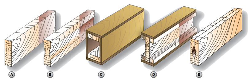
 Wooden spars are usually made from spruce. They can be generally classified into four different types by their cross-sectional configuration. As shown in Figure 22.16.2‑5, they may be (A) solid, (B) box shaped, (C) partly hollow, or (D) in the form of an I-beam.
Lamination of solid wood spars is often used to increase strength. Laminated wood can also be found in box shaped spars. The spar in Figure 22.16.2‑5 (E) has had material removed to reduce weight but retains the strength of a rectangular spar. As can be seen, most wing spars are basically rectangular with the long dimension of the cross-section oriented up and down in the wing.
 FAA-H-8083-31, 2012)
 Currently, most manufactured aircraft have wing spars made of solid extruded aluminum or aluminum extrusions riveted together to form the spar.
 FAA-H-8083-31, 2012)
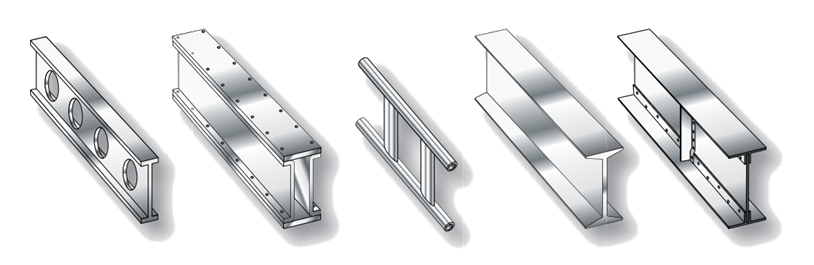
 Figure 22.16.2‑7 shows examples of metal wing spar cross-sections. In an I–beam spar, the top and bottom of the I–beam are called the caps and the vertical section is called the web. The entire spar can be extruded from one piece of metal but often it is built up from multiple extrusions or formed angles. The web forms the principal depth portion of the spar and the cap strips (extrusions, formed angles, or milled sections) are attached to it.
 FAA-H-8083-31, 2012)
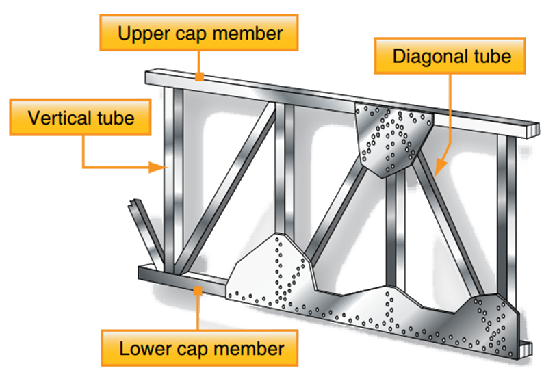
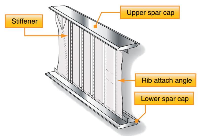
 Together, these members carry the loads caused by wing bending, with the caps providing a foundation for attaching the skin. Although the spar shapes in Figure 22.16.2‑7 are typical, actual wing spar configurations assume many forms. For example, the web of a spar may be a plate, or a truss as shown in Figure 22.16.2‑6. It could be built up from lightweight materials with vertical stiffeners employed for strength. Figure 22.16.2‑8.
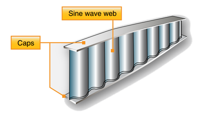
It could also have no stiffeners but might contain flanged holes for reducing weight but maintaining stiffness. Some metal and composite wing spars retain the I-beam concept but use a sine wave web. Figure 22.16.2‑10.
 FAA-H-8083-31, 2012)
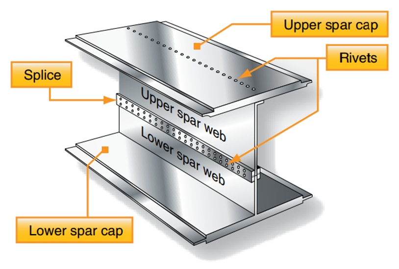
 Additionally, fail-safe spar web design exists. Fail-safe means that should one member of a complex structure fail, some other part of the structure assumes the load of the failed member and permits continued operation. A spar with failsafe construction is shown in Figure 22.16.2‑9. This spar is made in two sections. The top section consists of a cap riveted to the upper web plate. The lower section is a single extrusion consisting of the lower cap and web plate.
 FAA-H-8083-31, 2012)
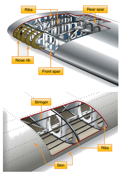
 These two sections are spliced together to form the spar. If either section of this type of spar breaks, the other section can still carry the load. This is the fail-safe feature. Most wings have two spars. One spar is usually located near the front of the wing, and the other about two-thirds of the distance toward the wing’s trailing edge. Regardless of type, the spar is the most important component of the wing. The spar carries the accumulated vertical load caused by the lift force on the wing. At the wing root this load can be very large. See Figure 22.16.2‑11.
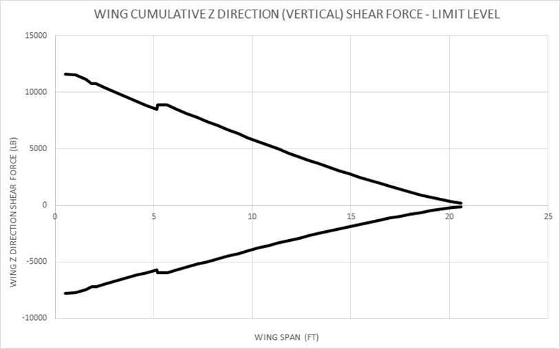
Note that positive shear force indicates up-bending on the wing which results from a positive ‘g’ maneuver (pitching nose up) or positive gust event. Negative shear force indicates wing down-bending from a negative ‘g’ maneuver (pitching nose down) or negative gust event.
In general, is it idealized that the vertical load created by positive and negative lift on the wing is carried by the vertical web of the wing spar or spars.
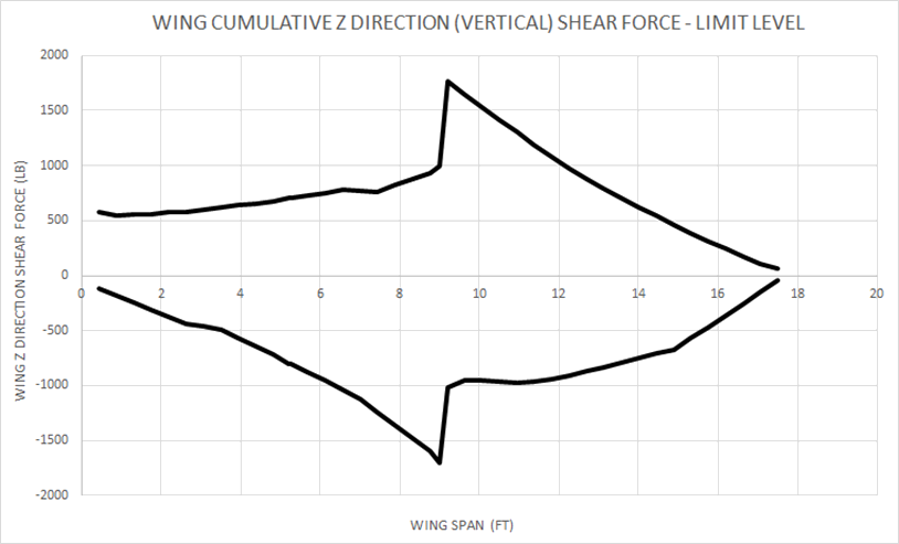
The peak vertical shear force at the wing root is greatly reduced when using a strut to support the wing. See Figure 22.16.2‑12.
Composite wing spars use high modulus carbon unidirectional fibers in the spar caps to carry the wing bending loads and to give maximum stiffness to the wing. The spar web is often biased towards +/- 45 degree woven composite carbon or glass to transfer the vertical shear loads.
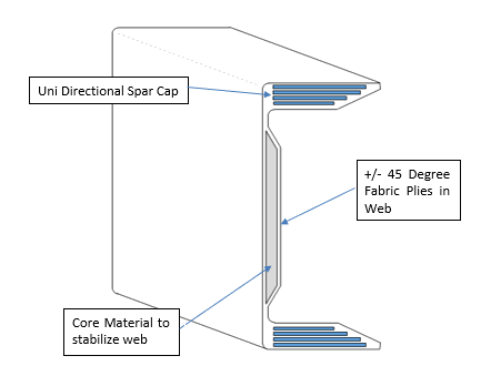
The spar web can be stabilized for shear buckling with honeycomb or foam core, or with bonded or fastened stiffeners.
If the fuel is carried in the wing of the aircraft the same means of resisting buckling of the web help to add strength to resist the out of plane loads on the spar web caused by the hydrostatic pressure of the fuel.
22.16.2.2. Wing Ribs
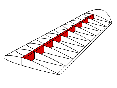
Ribs are the structural crosspieces that combine with spars and stringers to make up the framework of the wing. They usually extend from the wing leading edge to the rear spar or to the trailing edge of the wing. The ribs give the wing its cambered shape and help to transmit the air load from the skin and stringers to the spars.
Wing ribs are also used to help resist the pressure loads cause by carrying fuel in the wing. They are also used to help stabilize the skin in shear and compression buckling. They are more effective in helping the skin resist shear buckling because the ribs are aligned perpendicular to the compression loads in the skin which act in the spanwise direction.
Similar ribs are also used in ailerons, elevators, rudders, and stabilizers.
Wing ribs are usually manufactured from wood, metal or composite. Aircraft with wood wing spars may have wood or metal ribs while most aircraft with metal spars have metal ribs. Wood ribs are usually manufactured from spruce. The three most common types of wooden ribs are the plywood web, the lightened plywood web, and the truss types.
 FAA-H-8083-31, 2012)
 Of these three, the truss type is the most efficient because it is strong and lightweight, but it is also the most complex to construct. Figure 22.16.2‑14 shows wood truss web ribs and a lightened plywood web rib. Wood ribs have a rib cap or cap strip fastened around the entire perimeter of the rib. It is usually made of the same material as the rib itself. The rib cap stiffens and strengthens the rib and provides an attaching surface for the wing covering. In Figure 22.16.2‑14 (A), the cross-section of a wing rib with a truss-type web is illustrated. The dark rectangular sections are the front and rear wing spars. Note that to reinforce the truss, gussets are used. In Figure 22.16.2‑14 (B), a truss web rib is shown with a continuous gusset. It provides greater support throughout the entire rib with very little additional weight. A continuous gusset stiffens the cap strip in the plane of the rib. This aids in preventing buckling and helps to obtain better rib/skin joints where nail-gluing is used. Such a rib can resist the driving force of nails better than the other types.
Continuous gussets are also more easily handled than the many small separate gussets otherwise required. Figure 22.16.2‑14 (C) shows a rib with a lighten plywood web. It also contains gussets to support the web/cap strip interface. The cap strip is usually laminated to the web, especially at the leading edge.
A wing rib may also be referred to as a plain rib or a main rib. Wing ribs with specialized locations or functions are given names that reflect their uniqueness. For example, ribs that are located entirely forward of the front spar that are used to shape and strengthen the wing leading edge are called nose ribs or false ribs. False ribs are ribs that do not span the entire wing chord, which is the distance from the leading edge to the trailing edge of the wing.
Wing butt ribs may be found at the inboard edge of the wing where the wing attaches to the fuselage. Depending on its location and method of attachment, a butt rib may also be called a bulkhead rib or a compression rib if it is designed to receive compression loads that tend to force the wing spars together. Since the ribs are laterally weak, they are strengthened in some wings by tapes that are woven above and below rib sections to prevent sidewise bending of the ribs. Drag and anti-drag wires may also be found in a wing. Figure 22.16.2‑15, they are shown crisscrossed between the spars to form a truss to resist forces acting on the wing in the direction of the wing chord. These tension wires are also referred to as tie rods. The wire designed to resist the backward forces is called a drag wire; the anti-drag wire resists the forward forces in the chord direction. Figure 22.16.2‑15 illustrates the structural components of a basic wood wing.
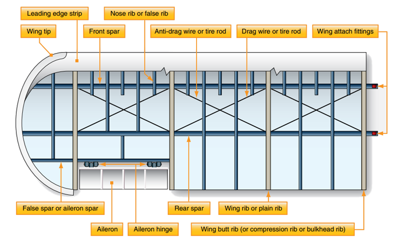 FAA-H-8083-31, 2012)
 At the inboard end of the wing spars is some form of wing attach fitting as illustrated in Figure 22.16.2‑15. These provide a strong and secure method for attaching the wing to the fuselage. The interface between the wing and fuselage is often covered with a fairing to achieve smooth airflow in this area.
22.16.2.3. Wing Skin
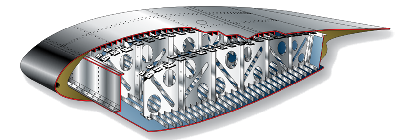
Often, the skin on a wing is designed to carry part of the flight and ground loads in combination with the spars and ribs. This is known as a stressed-skin design. The all-metal, full cantilever wing section illustrated in Figure 1-35 shows the structure of one such design. The lack of extra internal or external bracing requires that the skin share some of the load. Notice the skin is stiffened to aid with this function.
 FAA-H-8083-31, 2012)
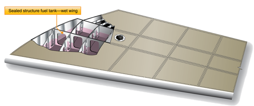
 Fuel is often carried inside the wings of a stressed-skin aircraft. The joints in the wing can be sealed with a special fuel resistant sealant enabling fuel to be stored directly inside the structure. This is known as wet wing design. Alternately, a fuel-carrying bladder or tank can be fitted inside a wing. Figure 1-36 shows a wing section with a box beam structural design such as one that might be found in a transport category aircraft. This structure increases strength while reducing weight. Proper sealing of the structure allows fuel to be stored in the box sections of the wing. The wing skin on an aircraft may be made from a wide variety of materials such as fabric, wood, or aluminum. But a single thin sheet of material is not always employed. Chemically milled aluminum skin can provide skin of varied thicknesses.
 FAA-H-8083-31, 2012)
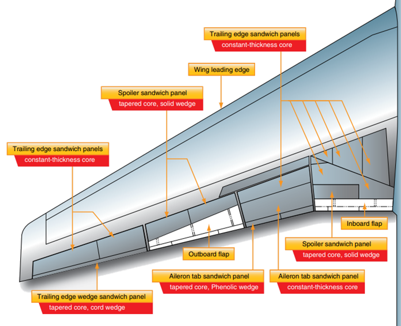
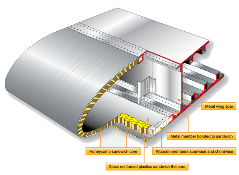
 On aircraft with stressed-skin wing design, honeycomb structured wing panels are often used as skin. A honeycomb structure is built up from a core material resembling a bee hive’s honeycomb which is laminated or sandwiched between thin outer skin sheets. Figure 1-37 illustrates honeycomb panes and their components. Panels formed like this are lightweight and very strong. They have a variety of uses on the aircraft, such as floor panels, bulkheads, and control surfaces, as well as wing skin panels. Figure 1-38 shows the locations of honeycomb construction wing panels on a jet transport aircraft.
 FAA-H-8083-31, 2012)
 A honeycomb panel can be made from a wide variety of materials. Aluminum core honeycomb with an outer skin of aluminum is common. But honeycomb in which the core is an Arimid® fiber and the outer sheets are coated Phenolic® is common as well. In fact, a myriad of other material combinations such as those using fiberglass, plastic, Nomex®, Kevlar®, and carbon fiber all exist. Each honeycomb structure possesses unique characteristics depending upon the materials, dimensions, and manufacturing techniques employed. Figure 1-39 shows an entire wing leading edge formed from honeycomb structure.
 FAA-H-8083-31, 2012)