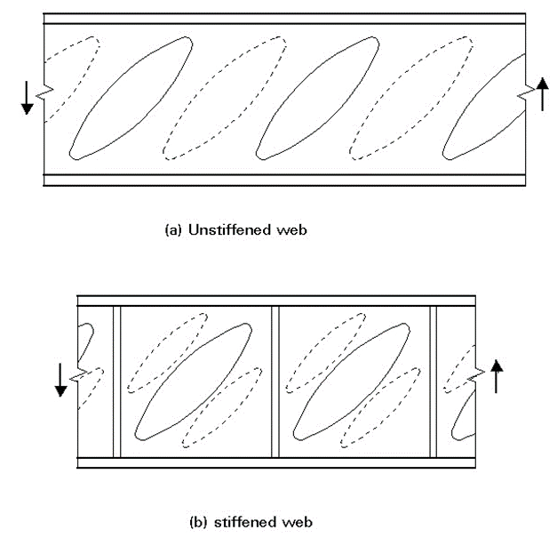
A web is a panel supported along all 4 sides, it can be the typical shear web component of an I or C-section beam. A web can be continuous or broken into smaller panels by vertical stiffeners.
15.2.3.1. Shear Buckling Allowable Stress
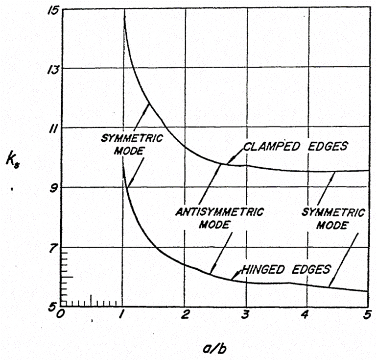
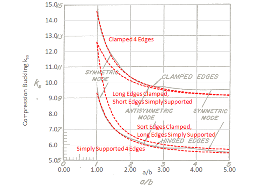
The shear buckling coefficient, ks, can be found once the panel aspect ratio is known from the following figure:
 NACA-TN-3781, 1957)
 There are some good theoretical approximations to the shear buckling coefficient curves. These are as follows:
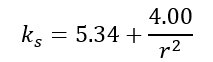
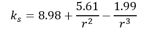
For a panel simply supported on four edges:
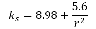
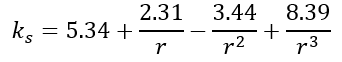
For a panel clamped on four edges:
For a panel clamped on the long edges and simply supported on short edges:
For a panel clamped on the short edges and simply supported on long edges:
Where: r = a/b
The theoretical curves are shown in the following figure:
These Curves are plotted and compared with the ‘classic’ curves from (![]() NACA-TN-3781, 1957) in the following spreadsheet:
NACA-TN-3781, 1957) in the following spreadsheet:
Figure 15.2.3‑3 shows that the theoretical approximations are a good fit to the existing curves. It is recommended that the theoretical approximations are used.
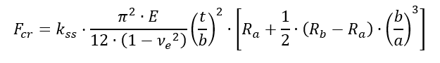
The spreadsheets for derivation of the shear buckling allowable use the theoretical approximations for k in the following expression:
The simplest approach to determine the panel shear buckling allowable, and the approach that is commonly used for initial sizing, is to assume that and the panel is simply supported.
Using this simple approach if Fcr exceeds Fsy , the shear yield allowable stress for the panel, then limit Fcr to Fsy . A comparison between this simple assumption and the calculated elasto-plastic shear buckling allowable for a typical aluminum is shown in Figure 15.2.3‑7.
A spreadsheet method for simple shear buckling of a web is given at the link below:
15.2.3.2. Shear Buckling Allowable Stress with Varying Panel Rotational Edge Fixity
The method can be refined in the following way for panel edge rotational fixity:
Panel edge fixity is a measure of edge rotational stiffness relative to the out-of-plane stiffness of the web being considered. What could be considered to provide adequate out-of-plane stiffness in translation and rotation for a 0.025in thick aluminum web may not be considered to provide any support at all for a 0.25in thick steel web. A rational measure of relative panel edge stiffness is required.
According to (![]() NACA-TN-2661, 1952) Section 3.6 the simply supported panel shear buckling coefficient can be modified for a range of edge rotational fixity from simply supported to built-in with the following expression:
NACA-TN-2661, 1952) Section 3.6 the simply supported panel shear buckling coefficient can be modified for a range of edge rotational fixity from simply supported to built-in with the following expression:
Where Ra and Rb are the rotational edge fixity coefficients for sides a and b of the web respectively. Where 1 = simply supported and 1.62 = fully fixed.
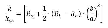
The simply supported shear buckling coefficient can be modified using the following expression:
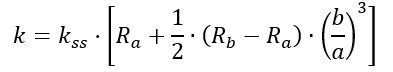
The modifier to the simply supported shear buckling coefficient can be expressed as:
Note that when Ra and Rb are equal to 1.62 (corresponding to fully fixed) the k value is close to, but not exactly the same value as the upper line in Figure 15.2.3‑2. This is acceptable, and the difference is not significant.
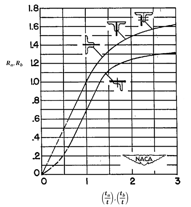
The values for Ra and Rb can be estimated from the following chart.
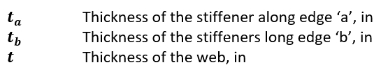
Where:
 NACA-TN-2661, 1952)
 As before, if Fcr exceeds Fsy then limit Fcr to Fsy .
Note that, according to Figure 15.2.3‑4, the values of Ra and Rb can be less than one. This would reduce the k value to below the value for the simply supported edge. This implies that if the panel edge members are not sufficiently thick, the translational stiffness of the panel edge is not sufficient.
If results for Ra and Rb are less than 1.0 this is considered to be a failing structure; redesign is required to improve the translational stiffness of the panel edge members.
A spreadsheet method for shear buckling of a web with varying edge rotational restraints is given at the link below:
15.2.3.3. Shear Buckling Allowable Stress with Full Elasto-Plastic Material Data
If the calculated shear buckling stress is approaching the shear yield stress (Fsy) of the material, the elastic shear buckling allowable could be optimistic. If a more nuanced approach than limiting the buckling stress to is required, the shear buckling allowable should be modified using the plasticity correction factor .
For Shear buckling the plasticity correction factor is Gs/G – that is the secant shear modulus divided by the material shear modulus. This data can be plotted for a range of stresses and an ‘elastic vs plastic’ buckling stress for any material can be plotted.
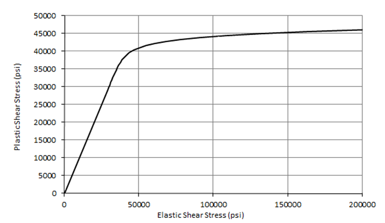
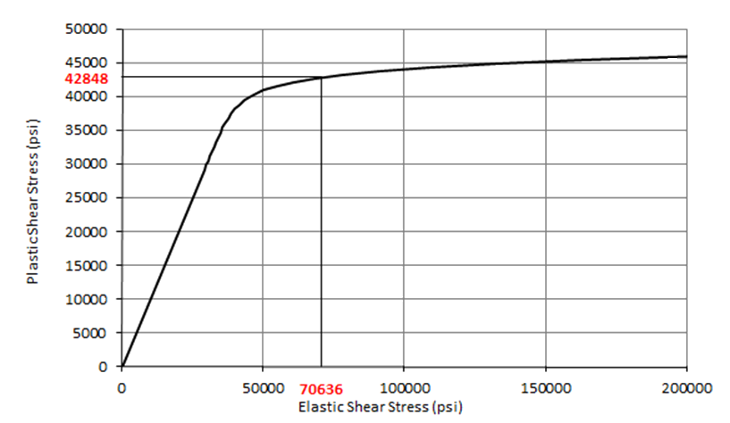
Once the graph has been plotted the elastic shear buckling allowable can be plotted on the x-axis, project upwards to the curve and read across to the Y-axis to give the shear buckling allowable corrected for plasticity.
This is shown on the figure below where the elastic shear buckling stress of 70636 psi is corrected to 42848 psi.
Superimposing the simpler approach of limiting Fcr to Fsy over the elastic vs plastic shear buckling stress curve gives the following result:
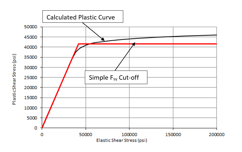
For the sample material (and for most ductile materials) the simple approach does give a reasonable approximation to the correctly calculated plastic buckling allowable. A spreadsheet for this method is available at the link below:
15.2.3.4. Effect of Central Hole on Panel Shear Buckling Allowable
This section is based on the work in (![]() NASA-CR-132548). The reduction in shear buckling allowable is related to the ratio of the hole size to the panel size, or the d/b ratio.
NASA-CR-132548). The reduction in shear buckling allowable is related to the ratio of the hole size to the panel size, or the d/b ratio.
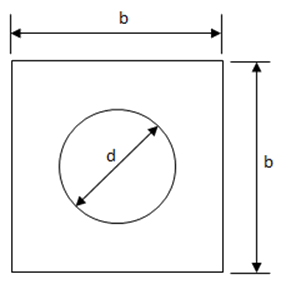
Where ‘d’ is the circular hole diameter and ‘b’ is the ruling dimension of the panel. When the panel is not square the dimension ‘b’ can be assumed to be the minimum panel dimension.
A good curve fit to the experimental test results in (![]() NASA-CR-132548) is the function:
NASA-CR-132548) is the function:
K/K0 = e-1.585 x d/b. This relationship is shown in the following figure and the linked spreadsheet.
15.2.3.5. Collapse of Shear webs with Flanged Circular Holes
This section is based on (![]() NACA-WR-L-323, 1942) . The collapsing shear stress of a rectangular web is given by the following expression:
NACA-WR-L-323, 1942) . The collapsing shear stress of a rectangular web is given by the following expression:
Where the parameters are defined as follows:
 NACA-WR-L-323, 1942)
 This method is available in spreadsheet form here:
15.2.3.6. Assessment of Panel Breaker Effectivity
This section is largely taken from (![]() NACA-TN-862, 1942). This reference comprises of an experimental study of 60 different tests of 17S-T built-up aluminum shear beams. This material is equivalent to a modern 2017 aluminum alloy.
NACA-TN-862, 1942). This reference comprises of an experimental study of 60 different tests of 17S-T built-up aluminum shear beams. This material is equivalent to a modern 2017 aluminum alloy.
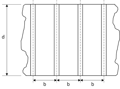
This reference examined a range of different panel configurations and notes the effect of the stiffener configuration on the extent of the out-of-plane deflection of the web and the stiffener.
The reference then proposes a rule that governs the acceptable stiffener 2nd moment of area based on the web panel dimensions and the web thickness.
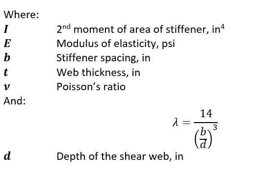
The expressions can be combined and arranged to give a criterion for the required stiffener 2nd moment of area:
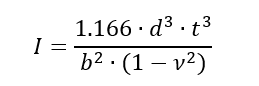
It is recommended that this check is used as a rough sizing approximation only, but it can be considered applicable to web buckling in shear, compression and bending. It is recommended that component testing or a higher order analysis is carried out to confirm the results of this analysis.
A spreadsheet method is given at the link below: