In general; composite mechanical joint strength must be based on a comprehensive test program. Specific strength data cannot be provided as there are many different materials and layup combinations.
However, general design guidelines are provided, and analysis methodologies can be discussed.
12.2.4.1. Mechanical Joints in Composite Panels – Design Guidelines
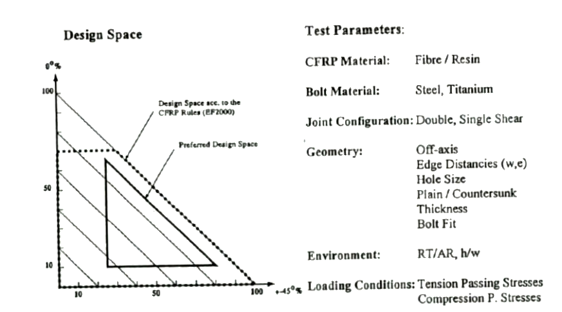
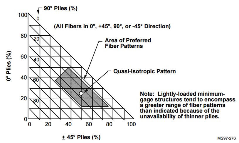
The makeup of the laminate is critical. In general, quasi-isotropic laminate is preferred, although deviations from perfect quasi-isotropy are permissible and will have limited effect on joint strength.
 NASA-NAS1-19347, 1997)
 Figure 12.2.4‑1: Lay-up Suitability for Bolt Installation
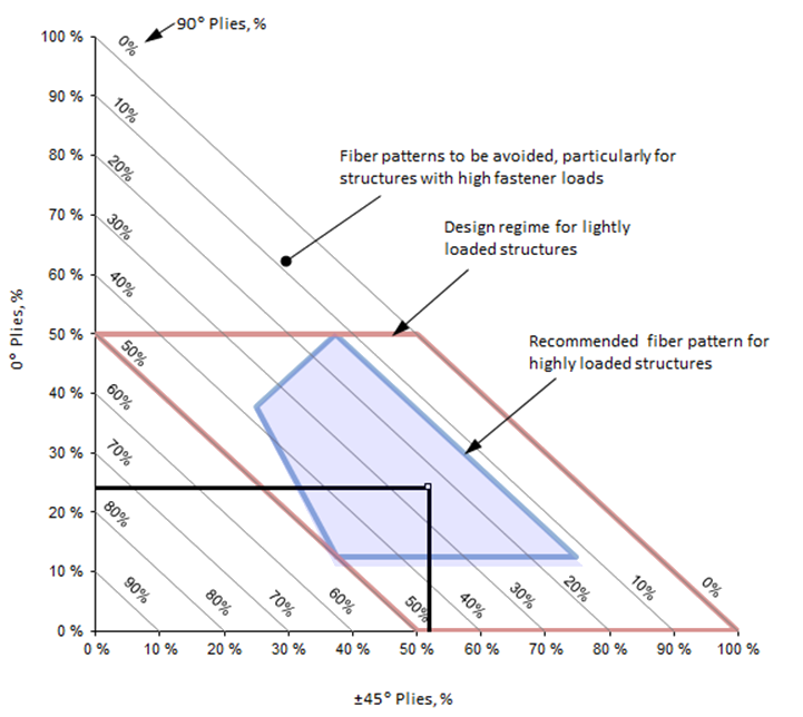
There are several versions of the appropriate envelope to use for layups (examples shown in the figures above). The recommended layup range is given in Figure 12.2.4‑2 and the following spreadsheet.
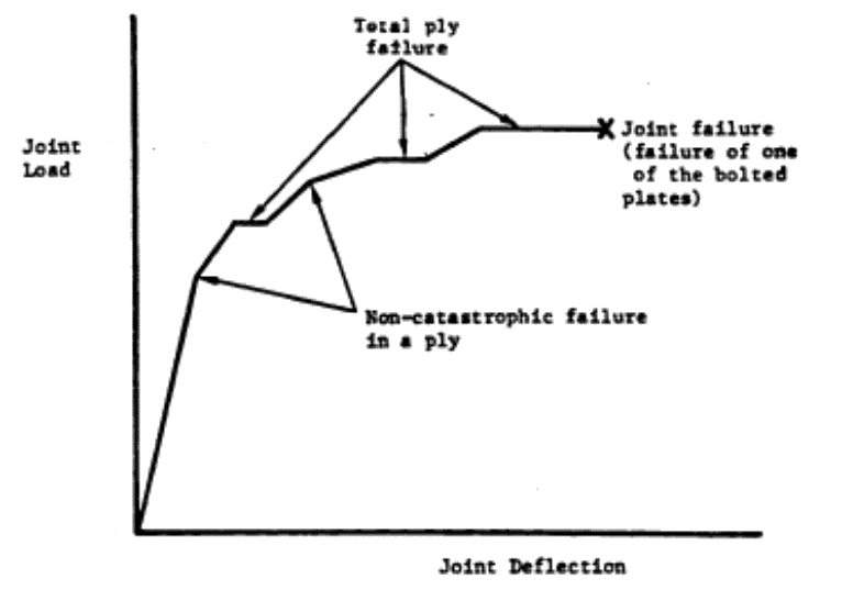
Bearing failure in a composite place is progressive and non-linear, this is shown in the following figure.
 AFWL-TR-86-3035, 1986)
 When testing and assessing specific joint configurations, it is recommended that the first failure is taken as the limit load level for the joint. This approach will demonstrate compliance with FAR 23.305(a) – The structure must be able to support limit loads without detrimental, permanent deformation. At any load, up to limit loads, the deformation may not interfere with safe operation.
The final joint failure load level can be taken as the ultimate strength.
Note on Shear-Out Strength of Mechanical Joints in Composite Panels
(![]() ARC-CP-1380, 1977) gives some excellent data for shear-out vs bearing strength for a series of tests on a range of laminate configurations.
ARC-CP-1380, 1977) gives some excellent data for shear-out vs bearing strength for a series of tests on a range of laminate configurations.
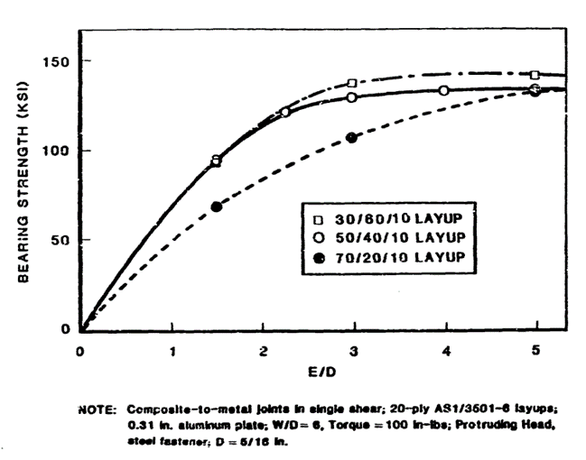
The first figure below is for a laminate close to quasi isotropic and below that is comparison data for biased laminate layups.
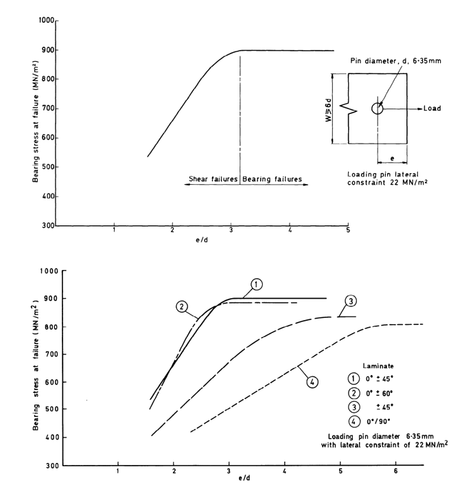 ARC-CP-1380, 1977)
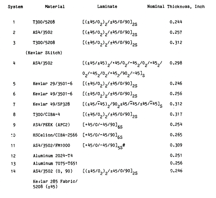
 This same behavior is duplicated in (![]() AFWL-TR-86-3035, 1986)
AFWL-TR-86-3035, 1986)
 AFWL-TR-86-3035, 1986)
 This shows that for quasi-isotropic carbon laminates (and laminates close to quasi-isotropic) and E/D of 3.0 will allow the joint to develop the bearing strength of the laminate.
12.2.4.2. In-Plane Strength for Mechanical Joints in Composite Sheets
For most structures the following simple joint strength for composite laminates can be used:
If the fastener size or joint configuration is not included in the specific project-approved test results, 50ksi can be used as a general bearing stress allowable for carbon fiber laminates in their worst environmental condition and 40ksi for glass fiber laminates in their worst environmental condition. As long as the t/D (thickness/Diameter) ratio is between 0.5 and 2 and the E/D (Edge Distance/Diameter) is greater than 3.0.
Note that the in-plane strengths for composite laminate sheets for protruding head fasteners can be applied to countersunk fasteners without modification.
12.2.4.3. Out-of-Plane Strength for Mechanical Joints in Composite Sheets
There is no reliable analytical method to determine the pull-through strength of fasteners in laminated composites. There is some public domain data that can serve as a useful sizing guide. (![]() NASA-TM-87603, 1985) is one of these.
NASA-TM-87603, 1985) is one of these.
The allowable data in this reference is slightly greater than that I have seen from test on several programs. Be sure to use the 1.15 fitting factor for calculations using values from this reference.
This data is developed using a 3/16in diameter 100o countersunk head titanium Huck fastener.
This testing was done with laminates from .244in to .317in thick and also for 2000 and 7000 series aluminum for comparison.This testing was done at room temperature. Environmental factors should be applied to these results.
 NASA-TM-87603, 1985)
 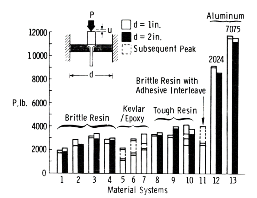 NASA-TM-87603, 1985)
 It is recommended that when considering a 3/16in countersunk fastener in 1/4in thick carbon laminate at room temperature strength of 1000lb is used.
The results of (![]() NASA-TM-87603, 1985) compare well with more recent reference that compares test results with a semi empirical hand method in (
NASA-TM-87603, 1985) compare well with more recent reference that compares test results with a semi empirical hand method in (![]() Pull-through Failure of Composite Joints, 2013).
Pull-through Failure of Composite Joints, 2013).
This method is defined as follows:
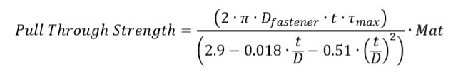
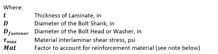
Note that this reference was solely concerned with pullout strength in carbon fiber laminate. This method correlated joint failure to the interlaminar shear strength of the laminate. It is noted that the interlaminar shear strength of a glass fiber laminate is similar to the interlaminar shear strength of a carbon fiber laminate with the same resin. Due to the increased flexibility of glass it is recommended that a 0.75 factor is applied.
The reference gives some correlation data to validate the method:
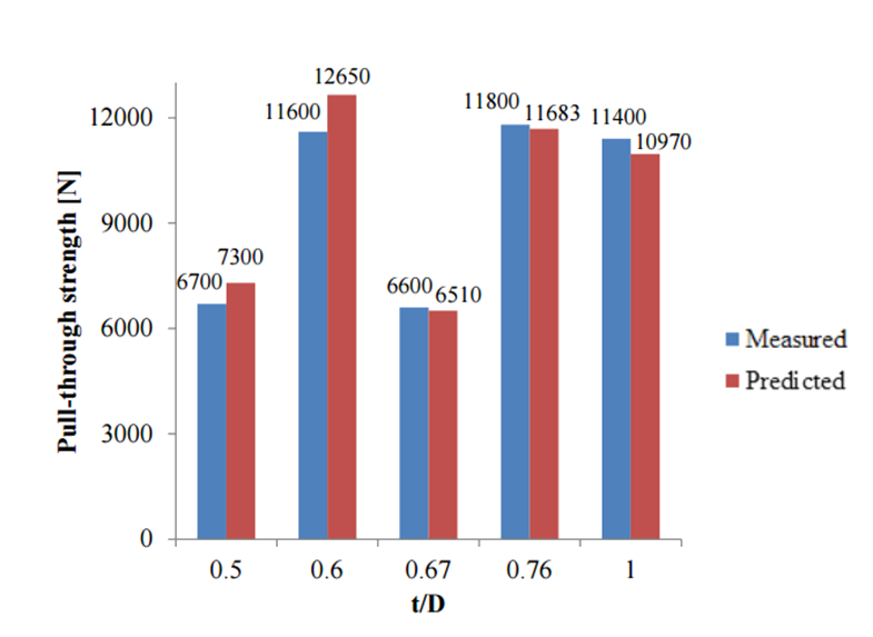 Pull-through Failure of Composite Joints, 2013)
 - The reader is reminded to make sure that if the interlaminar shear strength of the material at ETW is not available it should be derived in a conservative manner from available data.
- It is noted that in the available data countersunk fasteners show no appreciable difference in pull through strength when compared to protruding head bolts when the difference in head diameter between the types are accounted for.
- It is also noted that the reference considered largely quasi isotropic laminates. It is recommended that the local layup be as close to quasi-isotropic as possible.
This method is available in a spreadsheet here:
12.2.4.4. Mechanical Joint Design Check List
- Solid rivets and blind rivets should not be used to react significant tension loads.
- The tail diameter for solid rivets can be assumed to be 1.5 x the shank diameter.
- Note that aluminum (commonly used for solid rivets and blind rivets) has galvanic corrosion potential with carbon fiber and steel. Galvanic corrosion potential is increased by the presence of moisture and further increased by the presence of salt water.
- Do not mix different types of fasteners (i.e. solid rivets and bolts) in the same joint.
- In access panels and removable doors use a consistent grip length for all fasteners.
- Avoid design that places fastener threads in bearing for joints that carry a significant load. (See Section 12.2.7)
- In both metal and laminate composites that carry significant in-service loads, the countersunk depth should not exceed 70% of the sheet thickness.
- The edge distance in metal panels should be 2 x fastener shank diameter + positional tolerance.
- Where the service loads are low, the fastener edge distance in metal components may be reduced to 1.5 x the nominal fastener shank diameter + positional tolerance.
- ‘Spot facing’ in internal radii of machined metal components to allow for adequate fastener head/tail/collar/nut clearance is not recommended.
- Fastener pitch should be no less than 4 x the nominal fastener shank diameter.
Design Guidance Specific to Mechanically Fastened Laminate Composite Joints:
Note: The ideal laminate for mechanical joints is quasi-isotropic.
- Fastener edge distance in composite components should be a minimum of 3x the nominal fastener shank diameter with allowance for hole positional tolerance. This gives a minimum fastener edge distance in composite laminate components of 3x Diameter + .05in.
- In special circumstances, the fastener edge distance in composite laminate components may be reduced to 2.5x the nominal fastener shank diameter + .05in, in this case, additional analysis or other substantiation is required.
- Interference fits may not be used in composite components. It is recommended that clearance fit holes are used in all mechanical joints in composite laminate sheets.
- When using large diameter bolts (>0.25in) in composite laminates the installation torque should be limited, or other mitigations used, to avoid crushing the laminate.
- To avoid galvanic corrosion, it is recommended fastener materials used in carbon laminate composite sheets be Titanium, A286, PHI13-8MO, Monel or PH17-4. Titanium fasteners are preferred as they are the most galvanically compatible with carbon fiber composite.
- In composite-to-metal locations, corrosion barriers like fiberglass layers must be used.
- Do not buck rivets in composite structure.
- Countersunk fasteners develop greater in-plane strength than shear head fasteners in composite laminate joints.
- In fuel containment areas, joints must be sealed to be leak-proof. Fasteners must also be sealed to prevent arcing within the fuel cell in the event of a lightning strike.
- Fastener pitch must not be less than 4 x shank diameter as the interaction of the KT effect around each hole will interact and cause premature failure.
Note: Effort should be made to follow these guidelines. Deviation will require additional analysis and/or testing to validate.