The in-plane strength of mechanical joints in metal panels can be reliably predicted using available and approved strength data for the bearing strength of the sheet and the shear and tension strengths of the fasteners. The best source for this data is (![]() MIL-HNDBK-5H, 1998) Chapter 8.1.
MIL-HNDBK-5H, 1998) Chapter 8.1.
Useful data is shown below.
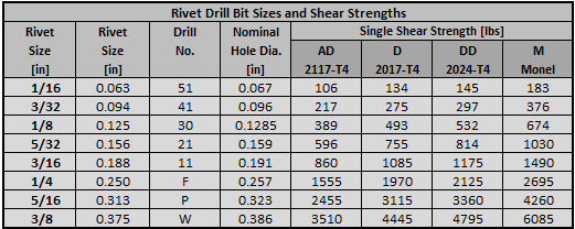
12.2.3.1. In-Plane Shear Strength of Rivets
Ref (![]() MIL-HNDBK-5H, 1998) Table 8.1.2(a) and Table 8.1.2(b)
MIL-HNDBK-5H, 1998) Table 8.1.2(a) and Table 8.1.2(b)
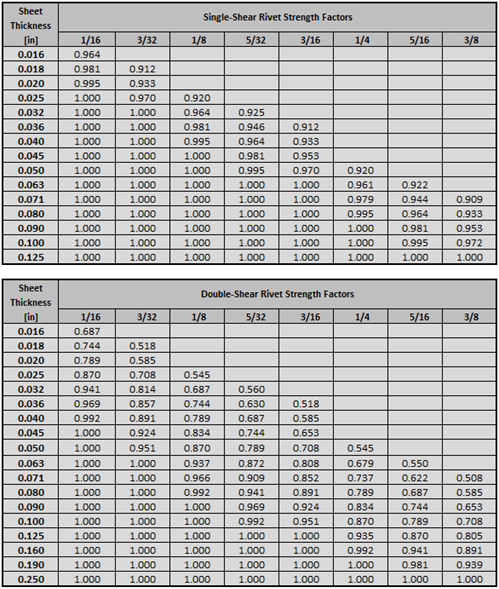
In calculating protruding-head rivet design shear strengths, the shear strength values obtained from Table 8.1.2(b) should be multiplied by the correction factors given in Table 8.1.2.1(b) – given below. This allows for the reduction in rivet shear strength resulting from high bearing stresses on the rivet at t/D ratios less than 0.33 for single-shear joints and 0.67 for double-shear joints.
Rivet joint strength can be calculated using this spreadsheet:
12.2.3.2. Out-of-Plane Strength for Mechanical Joints in Metal Panels
For metal sheets, the pull-out strength is determined by calculation. The pull-out strength is calculated as a ‘shear-out’ allowable.
The circumference of the outer diameter of the fastener head or collar/bolt (or washer if used) is calculated and combined with the thickness and shear allowable of the sheet material to determine the sheet tension allowable at the fastener. This is done for each sheet.
Sheet tension strength = Nominal Fastener Head Outer Diameter x π x Sheet Thickness x Fsu:

Where:
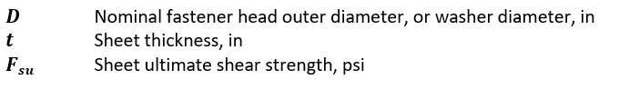
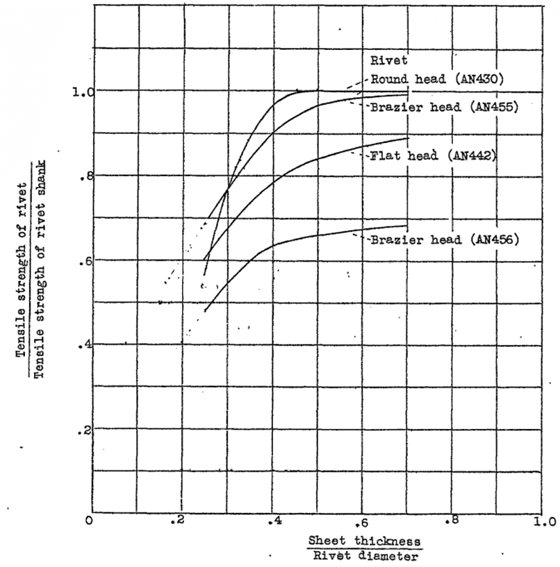
However, the tension strength of a joint can be significantly less than this based on the shape of the fastener head and the fastener material. (![]() NACA-TN-930, 1944) shows how much variation can occur between different type of rivets in pull-through strength. In the figure below the AN430 rivet is the equivalent of the common MS20470 solid rivet in use today.
NACA-TN-930, 1944) shows how much variation can occur between different type of rivets in pull-through strength. In the figure below the AN430 rivet is the equivalent of the common MS20470 solid rivet in use today.
 NACA-TN-930, 1944)
 It should also be noted that rivets should not be used as a primary tension load path. Even small tension loads can cause permanent deformation of the formed rivet tail. This can reduce the amount of clamp-up in the joint and significantly reduce the fatigue life of a riveted joint. For this reason, tension load on rivets should be limited to 20% of the ultimate shear strength of the rivet installation.