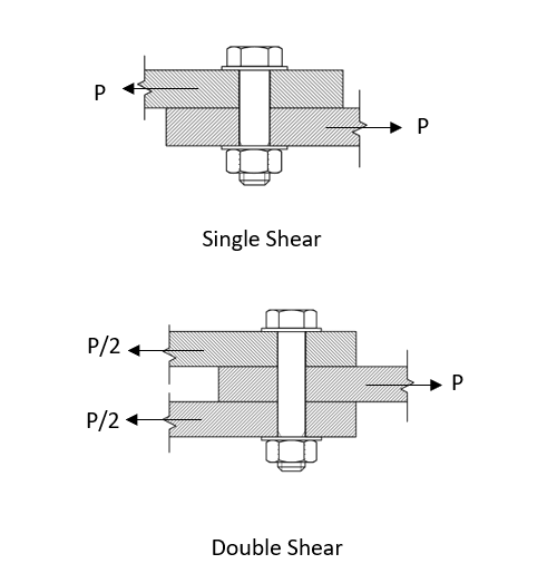
The in-plane or shear strength of a mechanically fastened joint includes consideration of the bearing failure of all items in the joint and the shear failure of the shank of the mechanical fastener. Depending on the joint configuration the in-plane strength may also include consideration of the bending failure of the shank of the mechanical fastener. If large out-of-plane deflections occur before failure; the fastener head can pull through the panels in the joint. The critical failure load of the joint will often include a combination of all of the above effects – but we call it bearing strength and assume the propensity for failure varies proportionally to the thickness (within limits).
The calculation of the in-plane strength of a joint may not include friction between items in the joint, the adhesive effects of liquid shim or fay surface sealant. This is not because these effects do not exist but rather that there is no process control applied during manufacturing to these aspects of the joint that guarantee any level of strength.
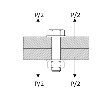
The out-of-plane or tension strength of the joint includes the pull-out strength of the sheets, the tension strength of the fastener (the least of the minimum tension area strength of the fastener shank/threaded portion and the shear out of the threads) and the tension/pullout strength of the nut, nut-panel or collar.
Note: There is a more complex method of determining the joint tension strength where the fastener pre-tension is accounted for. However, the effect of the fastener pre-load on the joint strength is not considered significant in this methodology.
Note: The published tension strengths for rivets are usually higher than the desirable tension load. A tension load in excess of 20% of the rivet shear strength can result in the deformation of the formed tail of the rivet and loss of joint clamp-up which significantly degrades the fatigue life of the riveted joint.
Note: The strength of each joint is subjected to the 1.5 ultimate load factor used for all structural analysis per FAR 23.303/25.303. Joints at fittings are also subjected to an additional 1.15 fitting factor per FAR 23.625/25.625.
Engineering judgment should be used when considering which checks to apply to a joint. If the tension load is low and it is not likely to significantly affect the overall margin of safety of the joint then is it acceptable to quote the shear strength margin of safety without considering the tension load effects – and vice-versa, if the applied shear load is much less than the tension load the tension margin of safety may be quoted without considering shear load effects.
The lower the overall load magnitude is, the greater the margin and the more leeway may be used in discriminating against particular lesser load effects in order to simplify the stress analysis. The converse is also true, if the margin of safety from one load effect alone is low then the other, much smaller, load effect may have to be considered and interacted with the primary load in order to ensure the structural integrity of the joint.
The following diagram shows how the in-plane strength of a mechanical joint varies with the thickness of the fastener sheets for protruding head and countersunk fastener in metal and for a general fastener in a fiber composite laminate.
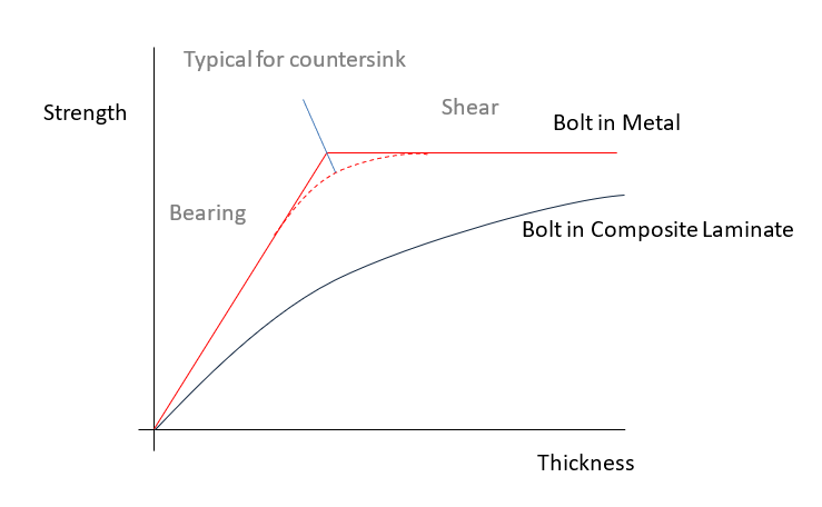
- The bearing strength (for protruding head fasteners) in metal components can be reliably calculated by the bearing area (Sheet Thickness x Fastener Diameter) multiplied by the bearing strength of the sheet material (Fbru).
- Note that the shear strength portion of Figure 12.2.2‑3 for metal joints is solely a function of the strength of the fastener shank in shear. That is the cross-sectional area of the shank multiplied by its ultimate shear strength (Fsu). This strength value is not affected by the thickness of the sheets in the joint.
- Note that in a typically formulated joint between sheets of composite laminate the fastener shank shear strength is not reached. The implication of this is that in a mechanically fastened joint between composite laminate sheets the joint failure mode will always be a failure in the composite laminate sheets. This is not always the case (it depends on the precise joint configuration: sheet thickness, sheet material, environmental condition, hole fit, fastener size and fastener material) but for typical mechanical joints in composite laminate components, it is a reasonable assumption.
- It can also be seen that the failure behavior of a mechanical fastener in a composite laminate sheet is not a simple bearing failure like that seen in metal sheets – the failure mode can be a combination of bolt bending and local bearing failure due to non-uniform bearing stresses combined with brittle bearing failure of the composite laminate material. There is no accurate way to develop these failure loads theoretically, therefore the strength of mechanical fasteners in composite laminates must be determined by test – or conservative assumptions must be applied where applicable test data does not exist.
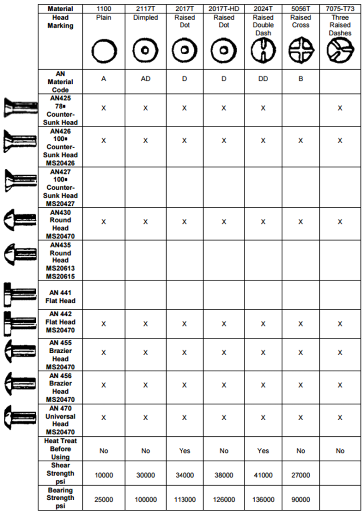
12.2.2.1. Aircraft Rivet Identification
See Section 27.1 for a more comprehensive definition of rivet types.
 AC43.13-1B, 1998)
 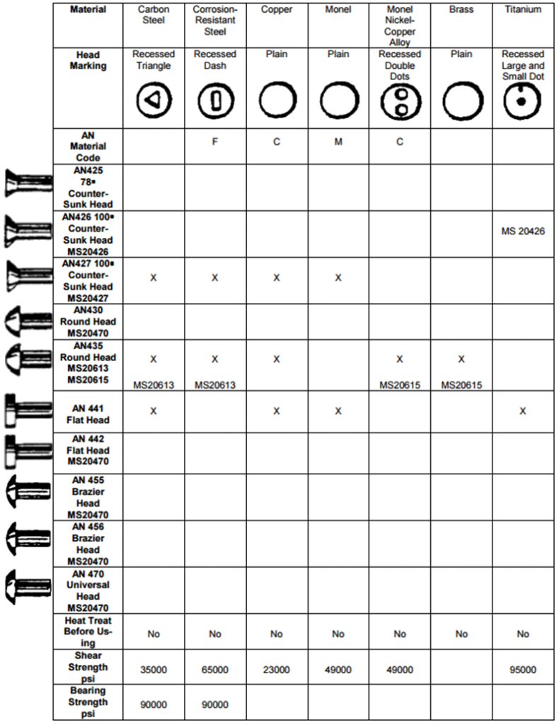 AC43.13-1B, 1998)
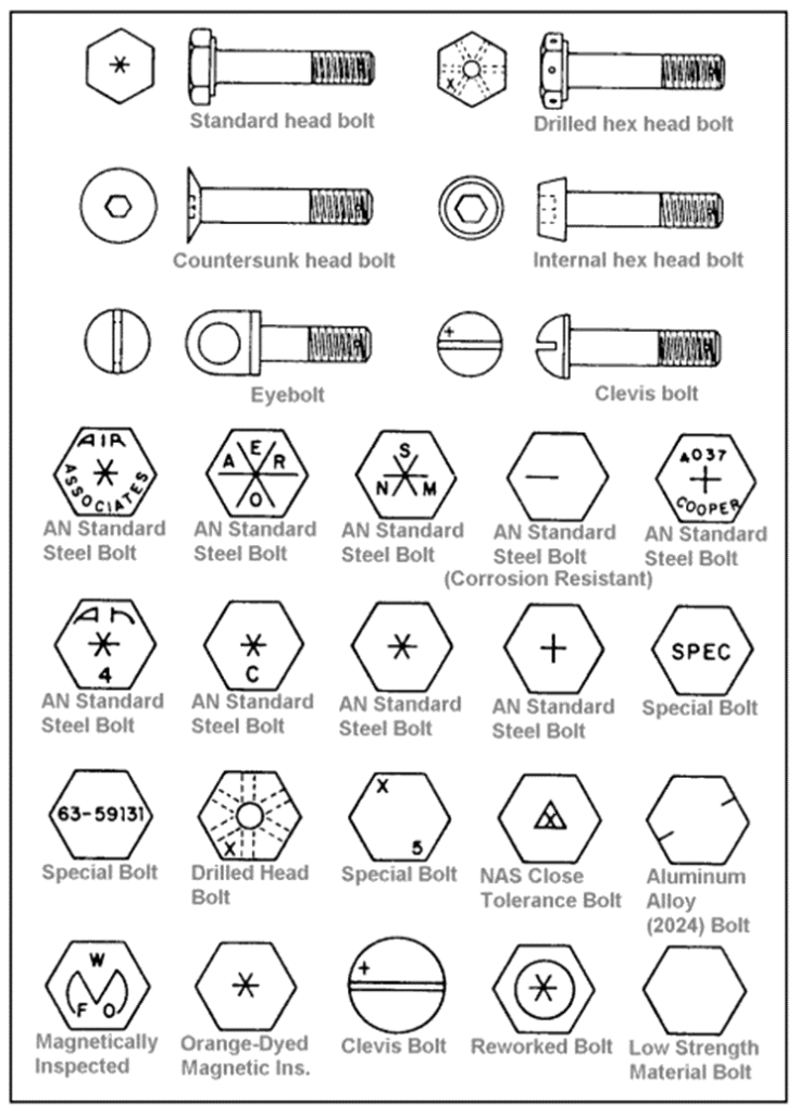
 12.2.2.2. Aircraft Bolt Identification
See Section 27.3 for a more comprehensive definition of bolt types.
 AC43.13-1B, 1998)
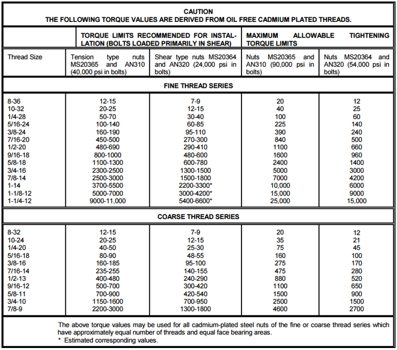
 12.2.2.3. Bolt Installation Torque Values
Threaded fasteners, unless specified on the drawing, must be torqued at installation to provide a pretension on the joint.
From (![]() AC43.13-1B, 1998):
AC43.13-1B, 1998):
“The importance of correct torque application cannot be overemphasized. Undertorque can result in unnecessary wear of nuts and bolts, as well as the parts they secure. Overtorque can cause failure of a bolt or nut from overstressing the threaded areas. Uneven or additional loads that are applied to the assembly may result in wear or premature failure. The following are a few simple, but important procedures, that should be followed to ensure that correct torque is applied”
 AC43.13-1B, 1998)