Nacelles (sometimes called “pods”) are streamlined enclosures used primarily to house the engine and its components. They usually present a round or elliptical profile to the wind thus reducing aerodynamic drag. On most single-engine aircraft, the engine and nacelle are at the forward end of the fuselage. On multiengine aircraft, engine nacelles are built into the wings or attached to the fuselage at the empennage (tail section).
Occasionally, an aircraft is designed with a nacelle in line with the fuselage aft of the passenger compartment. Regardless of its location, a nacelle contains the engine and accessories, engine mounts, structural members, a firewall, and skin and cowling on the exterior to fare the nacelle to the wind. Some aircraft have nacelles that are designed to house the landing gear when retracted.
Retracting the gear to reduce drag is standard procedure on high-performance/ high-speed aircraft. The wheel well is the area where the landing gear is attached and stowed when retracted. Wheel wells can be in the wings and/or fuselage when not part of the nacelle. Figure 22.12.2‑1 shows an engine nacelle incorporating the landing gear with the wheel well extending into the wing root.
 FAA-H-8083-31, 2012)
 The framework of a nacelle usually consists of structural members like those of the fuselage. Lengthwise members, such as longerons and stringers, combine with horizontal/vertical members, such as rings, formers, and bulkheads, to give the nacelle its shape and structural integrity. A firewall is incorporated to isolate the engine compartment from the rest of the aircraft. This is usually a stainless steel or titanium bulkhead that contains a fire in the confines of the nacelle rather than letting it spread throughout the airframe. Figure 22.12.2‑1.
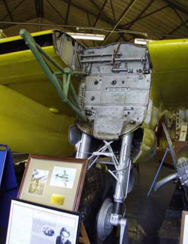
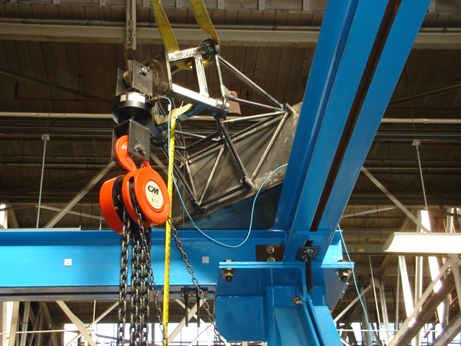
Engine mounts are also found in the nacelle. These are the structural assemblies to which the engine is fastened. They are usually constructed from chrome/molybdenum 4130 or 4140 steel tubing in light aircraft and forged chrome/nickel/ molybdenum assemblies in larger aircraft, Figure 22.12.2‑2.
The exterior of a nacelle is covered with a skin or fitted with a cowling which can be opened to access the engine and components inside. Both are usually made of sheet aluminum or magnesium alloy with stainless steel or titanium alloys being used in high-temperature areas, such as around the exhaust exit. Regardless of the material used, the skin is typically attached to the framework with rivets.
Cowling refers to the detachable panels covering those areas into which access must be gained regularly, such as the engine and its accessories. Cowl flaps are moveable parts of the nacelle cowling that open and close to regulate engine temperature.
Composite cowlings are also used, usually with a tumescent, heat sensitive internal coating that expands to create a temporary insulating layer in the event of an engine fire. The ‘scrubbing’ effect of the cooling air flow on the outside surface of the cowlings help maintain structural integrity in the event of an engine fire.
There are many engine cowl designs. Figure 22.12.2‑3 shows an exploded view of the pieces of cowling for a horizontally opposed engine on a light aircraft.
 FAA-H-8083-31, 2012)
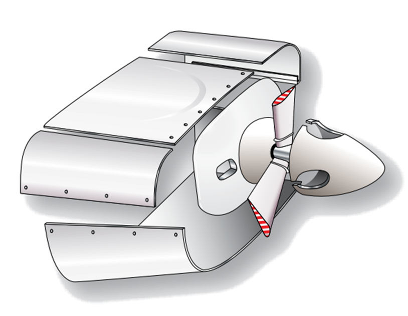
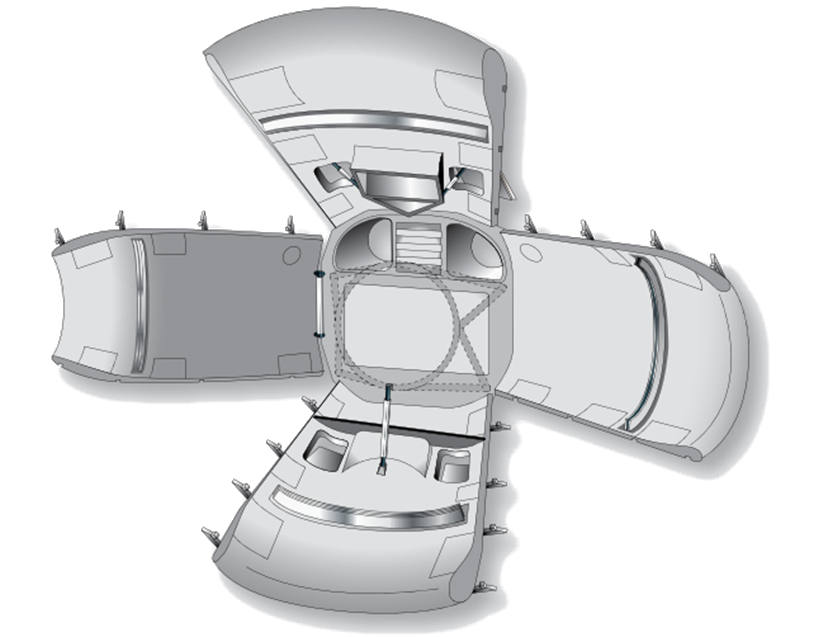
 The cowling is attached to the nacelle by means of screws and/or quick release fasteners. Some large reciprocating engines are enclosed by “orange peel” cowlings which provide excellent access to components inside the nacelle, Figure 22.12.2‑4.
These cowl panels are attached to the forward firewall by mounts which also serve as hinges for opening the cowl. The lower cowl mounts are secured to the hinge brackets by quick release pins. The side and top panels are held open by rods and the lower panel is retained in the open position by a spring and a cable. All of the cowling panels are locked in the closed position by over center steel latches which are secured in the closed position by spring-loaded safety catches.
 FAA-H-8083-31, 2012)
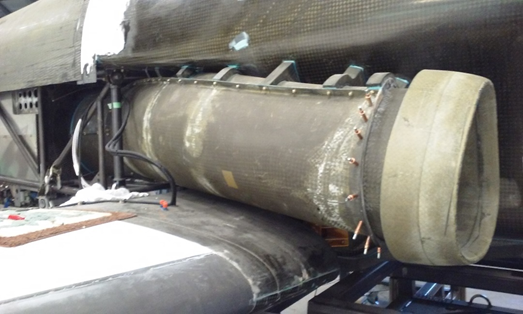
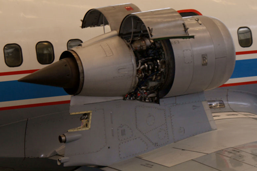
 An example of a turbojet engine nacelle can be seen in Figure 22.12.2‑5. The cowl panels are a combination of fixed and easily removable panels which can be opened and closed during maintenance. A nose cowl is also a feature on a jet engine nacelle. It guides air into the engine.
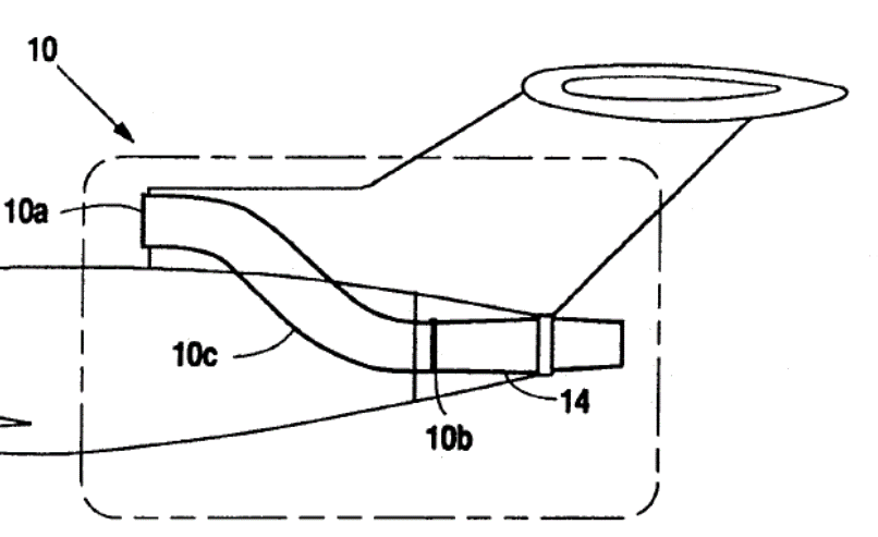
When the engine is buried inside the fuselage or tail of the aircraft the nose cowl or lip of the intake must be lengthened into a duct. In some cases the duct has to be split into a Y-Duct around the cabin area of the fuselage, Figure 22.12.2‑6.