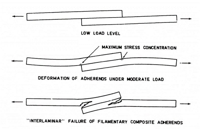
On test and in service; the desired failure mode is that the first ply (or more) should separate from the surface of the adherend.
 NASA-CR-112236, 1973)
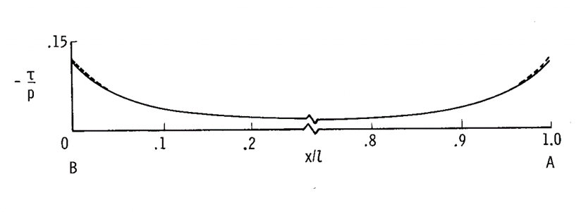
 The joint geometry affects the shear and peel stress in the joint; both of which peak at the edge of the adhesive.
 NASA-TN-D-7855, 1975)
 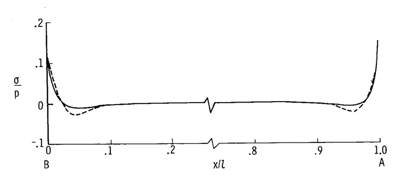 NASA-TN-D-7855, 1975)