The standard terms used to describe the components and parameters of bonded joints will be used throughout this section. They are defined below:
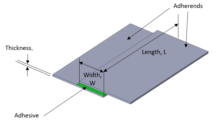
Adherends – The panels joined by the adhesive
Adhesive – The glue that joins the panels together
Width – The overlap length of the joint
Thickness – The depth of the adhesive between the two panels
Length – The distance the two panels are joined
Types of Joints:
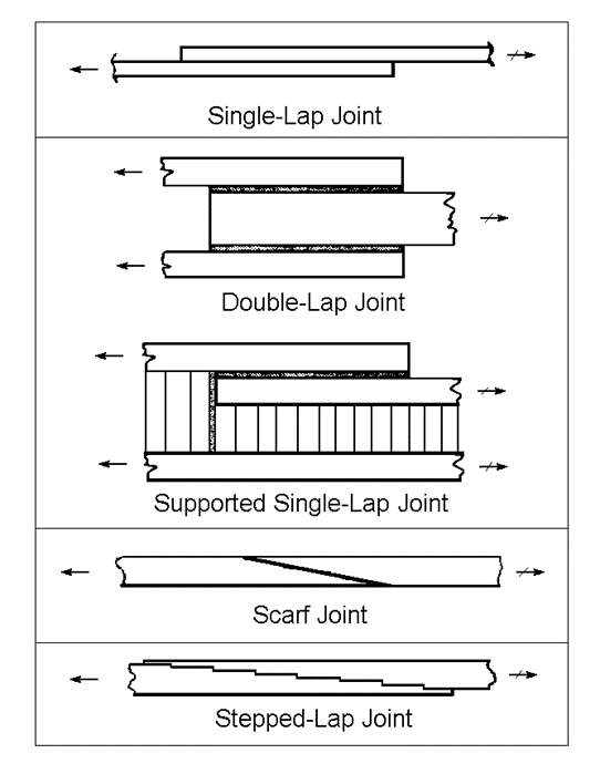
The most common type of adhesive joints in aircraft applications are single shear or single lap joints. These are the weakest joint configuration but it is the simplest to manufacture. They typically occur in wing ribs and wing spars to wing skin joints, fuselage frames to fuselage skins.
Single shear joints seem like the lazy option but in many circumstances, the simplicity and cost of design and manufacture make single shear joints prevalent in part 23 aircraft. In part 25 aircraft it is unusual to rely on the strength and reliability of an adhesive joint alone for primary load transfer. The discussion in this chapter is, therefore, concerning part 23 adhesive joint applications.
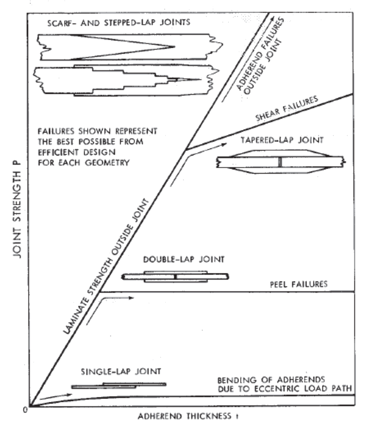
 NASA-CR-2218-1, 1974)
 Note that in Figure 12.1.1‑3 the single shear lap joint shows very low strength in comparison to the other pictured joint configurations.
The strength of adhesive joints depends on several factors:
- Strength of the adhesive.
- Adhesion to the surface by the adherends.
- This is governed by the composite material and the condition of the surface of the composite material. Use of peel ply can help this aspect of the joint strength.
- Thickness of the adhesive in the joint.
- The Thicker the joint, the lower the strength.
- Width of the joint.
- The wider the joint, the stronger it is.
- Environmental conditions.
- The critical condition can either be ETW (Extended Temperature Wet) or CTD (Cold Temperature Dry) depending on the response of the laminate and the adhesive to environmental conditions.
- Other factors such as the chemical compatibility of the adhesive with the resin matrix and the environmental conditions at the time the joint was manufactured.
The thickness of the adhesive (and of the composite panels) in the joint increases the offset in the joint, this offset creates a bending moment that causes peel stresses in the adhesive. This is one aspect of the joint that the designer can influence through stack up tolerances. Therefore tooling and fixturing tolerances should be carefully considered.
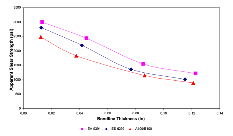
(![]() DOT/FAA/AR-01/33, 2001) gives valuable test data on the effect of adhesive thickness on the single shear strength of joints using common composite and metallic materials.
DOT/FAA/AR-01/33, 2001) gives valuable test data on the effect of adhesive thickness on the single shear strength of joints using common composite and metallic materials.
 DOT/FAA/AR-01/33, 2001)
 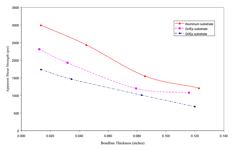 DOT/FAA/AR-01/33, 2001)
 The strength values from the above figures should not be used without confirmation by test for the materials and processes specific to the application you are considering.
Note that the above figures use the term ‘Apparent Shear Strength’, this is the simplest measure of the shear strength of the joint. It is the load applied on test divided by the area of the bond.
For the apparent shear strength to be used, the general configuration of the joint tested must be representative of, or conservative compared to, the design intended for the final application. A range of situations should be tested – varying adherend and adhesive thicknesses – to determine the minimum joint strength at the critical environmental condition.
The moment that creates peel load is reacted over the width of the joint. The wider the joint, the smaller the peel effect on the adhesive.
It follows that the geometry of the adhesive joint should be controlled to maximize adhesive width and minimize adhesive thickness.