Extract from: (![]() NASA TM X-73306, 1975)
NASA TM X-73306, 1975)
The application of theory to the design of actual cylindrical shells has been complicated by apparent discrepancies between theory and experiment.
For shells in which longitudinal compression of the cylinder wall predominates, the discrepancies can be quite large. For shells in which shear or circumferential compression predominates, the discrepancies are generally less severe but still large enough to require experimental programs to establish design data. The causes of such discrepancies are generally understood.
The primary source of error is the dependence of the buckling load of cylindrical shells on small deviations from the nominal circular cylindrical shape of the structure. Because the unloaded shape of a test specimen usually has not been stringently controlled, most test results for nominally identical specimens have larger scatter and fall below the theoretical values.
Another source of discrepancy is the dependence of buckling loads of cylindrical shells on edge values of longitudinal and circumferential displacements or forces. Also, because tangential edge conditions have not usually been precisely controlled in buckling tests, some of the scatter of test results can be attributed to this source. Current methods of establishing design data tend to treat both initial imperfections and edge conditions as random effects. Results from all available tests are considered together without regard to specimen construction or methods of testing and are analyzed to yield lower bound or statistical correction factors to be applied to simplified versions of the theoretical results. This technique has proved satisfactory to date for design purposes.
Within the limitations imposed by the state of the art, acceptable procedures for the estimation of critical loads on circular cylindrical shells are described in this section.
15.4.1.1. Buckling of Thin Simple Cylinders Under External Pressure
This section is taken from (![]() AFFDL-TR-69-42, 1986) Section 8.3.1.3.1. This method is similar to that defined in (
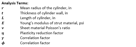
AFFDL-TR-69-42, 1986) Section 8.3.1.3.1. This method is similar to that defined in (![]() NASA TM X-73306, 1975) Section 3.1.1.5. The formula for the critical stress in short cylinders which buckle elastically under radial pressure is:
NASA TM X-73306, 1975) Section 3.1.1.5. The formula for the critical stress in short cylinders which buckle elastically under radial pressure is:
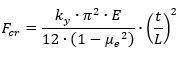
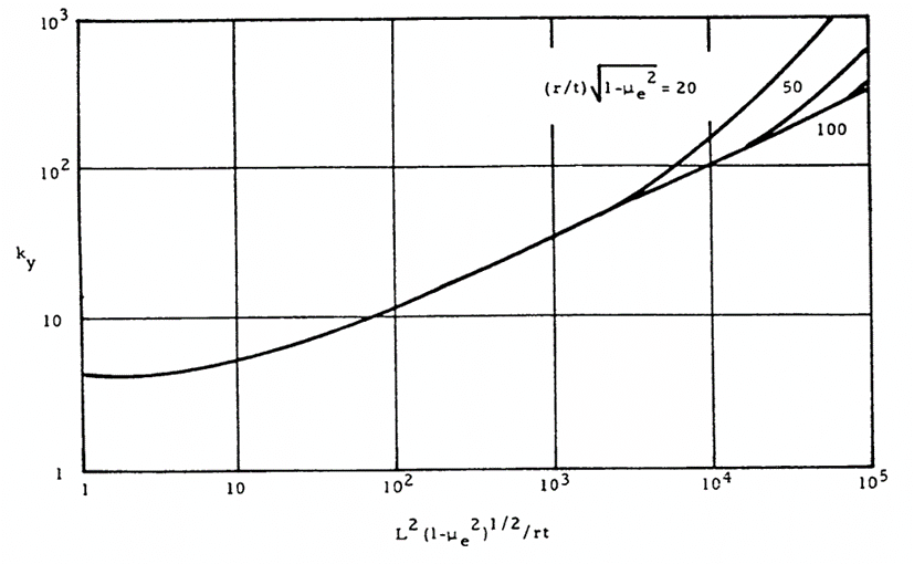
Where ky is obtained from the figure below:
 AFFDL-TR-69-42, 1986)
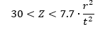
 The critical stress for long cylinders ( 100̇̇·t/r < (L/r)2 < 5 · r/t ) under external radial pressure is:
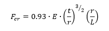
For very long cylinders, ( (L/r)2 < 5 · r · t ) the buckling stress is given by:
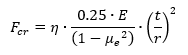
Where η is the plasticity reduction factor given in this case by:
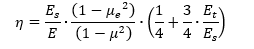
When the material remains in the elastic range the plasticity reduction factor = 1.0
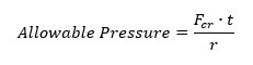
The allowable stress can be converted to an allowable pressure load using the expression:
This method is available in the linked spreadsheet below:
15.4.1.2. Buckling of Thin Simple Cylinders Under Axial Compression
This section is taken from (![]() NASA TM X-73306, 1975) Section 3.1.1.1.
NASA TM X-73306, 1975) Section 3.1.1.1.
This method predicts local buckling of short cylinders, longer cylinders should be checked as a column per section 15.3.
The design allowable compression buckling stress for a circular cylinder subjected to axial compression is given by:
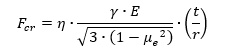
The lower boundary of the experimental data for cylinders in axial compression is given by the following expression:
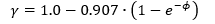
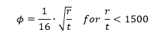
Where:
The relationship between γ and r/t is shown in the figure below:
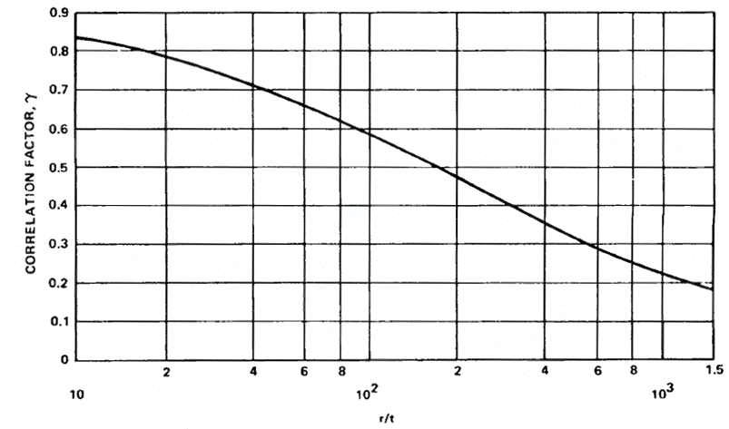 NASA TM X-73306, 1975)
 This method is available in the linked spreadsheet below:
15.4.1.3. Buckling of Thin Simple Cylinders Under Axial Compression and Internal Pressure
This section is taken from (![]() NASA TM X-73306, 1975) Section 3.1.1.2.
NASA TM X-73306, 1975) Section 3.1.1.2.
The modification to the buckling load is similar to the method in (![]() NACA-Report-1027) which compares analytical predictions and experimental results.
NACA-Report-1027) which compares analytical predictions and experimental results.
Buckling and collapse coincide for internally pressurized circular cylinders in axial compression, just as in the case of the un pressurized cylinder. Pressurization increases the buckling load in the following ways:
- The total compressive load must be greater than the tensile pressurization load p· π ·r² before buckling can occur.
- The destabilizing effect of initial imperfections is reduced.
The circumferential tensile stress induced by the pressurization inhibits the diamond buckling pattern, and, at sufficiently high pressurization the cylinder buckles in the classical axisymmetric mode at approximately the classical buckling stress.
It is recommended that the total load for buckling, unless substantiated by testing, be obtained by the addition of the pressurization load , the buckling load for the unpressurized cylinder (Reference Section 15.4.1.2) and an increase in the buckling load caused by pressurization; that is:
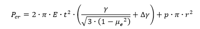
Where Δγ is obtained from figure below:
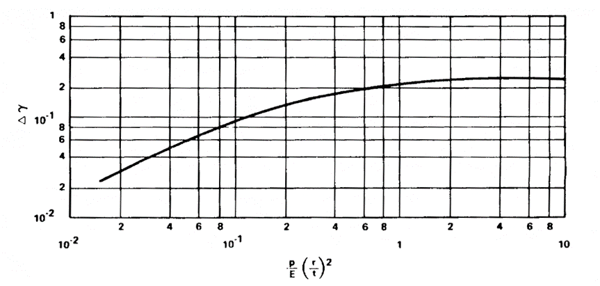 NASA TM X-73306, 1975)
 This method is available in the linked spreadsheet below:
15.4.1.4. Buckling of Thin Simple Cylinders Under Bending
The design allowable bending buckling stress for a circular cylinder subjected to axial compression is given by:
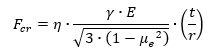
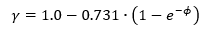
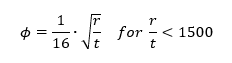
The procedure given for isotropic cylinders in axial compression may be used also to obtain the critical maximum stress for isotropic cylinders in bending, except that a correlation factor based on bending tests should be used. The correlation factor for the cylinder in bending is taken as:
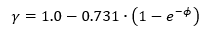
Where:
The relationship between γ and r/t is shown in the figure below:
 NASA TM X-73306, 1975)
 The Allowable Bending Moment can be calculated using the following expression:
This method is available in the linked spreadsheet below:
15.4.1.5. Buckling of Thin Simple Cylinders Under Bending and Internal Pressure
For thin-walled cylinders subjected to bending and internal pressure, it is recommended that the buckling moment be obtained by adding the moment-carrying capability of a pressurized membrane cylinder the buckling moment for the unpressurized cylinder:
As with a cylinder in bending:
The correlation factor for the cylinder in bending is taken as:
Where:
Where Δγ is obtained from figure 15.4.1.3.
This method is available in the linked spreadsheet below:
15.4.1.6. Buckling of Thin Simple Cylinders Under Shear or Torsion
This method is taken from (![]() NACA-TN-1344, 1947).
NACA-TN-1344, 1947).
The theoretical buckling coefficient for cylinders in torsion can be obtained from Figure 15.4.1‑5. The straight-line portion of the curve is given by the equation:
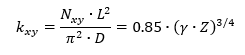
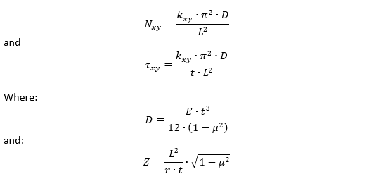
kxy is the buckling coefficient. This can be estimated in the following way. For very short cylinders the shear stress buckling coefficient approached the value for a flat plate. 5.34 when the edges are simply supported and 8.98 when the edges are clamped.
For long cylinders the buckling coefficients can be approximated by the following expressions.
For simply supported edges:
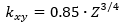
For clamped edges:
The range of validity of these formulas is:
For very high values of Z (< 20000) the value of increases slightly above the values predicted by the expressions above. This increase in is not characterized in this text, for more information see figure 1 of (![]() NACA-TN-1344, 1947).
NACA-TN-1344, 1947).
 NACA-TN-1344, 1947)
 15.4.1.7. Combined Buckling of Thin Simple Cylinders
The interaction between load effects is calculated using combinations of reserve factors.
Combined Compression and Bending: (![]() NASA TM X-73306, 1975)
NASA TM X-73306, 1975)
Axial Compression and External Pressure: (![]() NASA TM X-73306, 1975)
NASA TM X-73306, 1975)
Bending and Torsion: (![]() NASA TM X-73306, 1975)
NASA TM X-73306, 1975)
Axial Load and Torsion: (![]() NACA-TN-1345, 1947)
NACA-TN-1345, 1947)
For torsion/shear and compression:
Valid for simply supported and clamped edges in the range:
For torsion/shear and tension:
Valid for simply supported and clamped edges in the range: