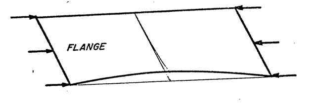
Flange compression buckling is a subset of compression buckling. The form of the physical detail is different and there are two other important differences.
- Generally, flanges are not considered to carry shear and so the interaction of shear and compression on flanges is usually not considered.
- Because flanges are usually relatively narrow there exist no methods for the effect of a (non-fastener) hole on the flange buckling stress. A hole in a flange would usually take up much of the flange cross section and render the flange ineffective as a structural detail.
15.2.6.1. Flange Compression Buckling Allowable Stress
 NACA-TN-3781, 1957)
 The simplest approach to flange compression buckling and the approach that is commonly used for initial sizing is to assume that and the panel is simply supported:
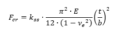
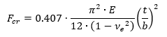
The kss for a flange of infinite length can be assumed to be 0.407 (Ref Figure 15.2.6‑2). Therefore, for a simple first check the following expression can be used:
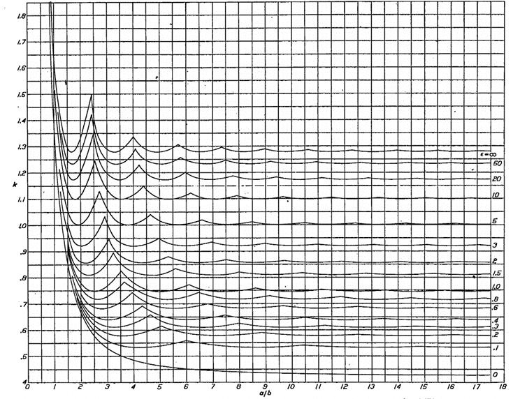
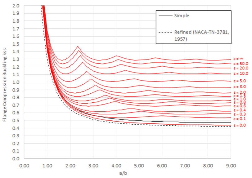
For finite length flanges the following approach can be used. The first figure is from (![]() NACA-TN-3781, 1957) and gives the buckling coefficients for flanges considering all edge conditions:
NACA-TN-3781, 1957) and gives the buckling coefficients for flanges considering all edge conditions:
 NACA-Report-734)
 The full expression for the flange compression buckling coefficient is given by the following expression (![]() NACA-Report-734) equation B-17:
NACA-Report-734) equation B-17:
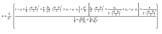
The coefficients are defined in the source reference.
This is plotted and shown on the next page compared to the simple coefficient expressions shown below.
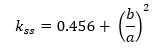
The flange compression buckling coefficient for a simply supported flange can be approximated by the following simple expressions:
(![]() NACA-TN-3781, 1957) gives the following expression for the flange buckling coefficient for a simply supported edge:
NACA-TN-3781, 1957) gives the following expression for the flange buckling coefficient for a simply supported edge:
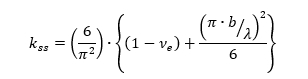
Where λ = The buckle half wave length, can be set to 1 for first buckling mode.
The flange compression buckling coefficient for a finite length simply supported flange can be found using Figure 15.2.6‑3 below:
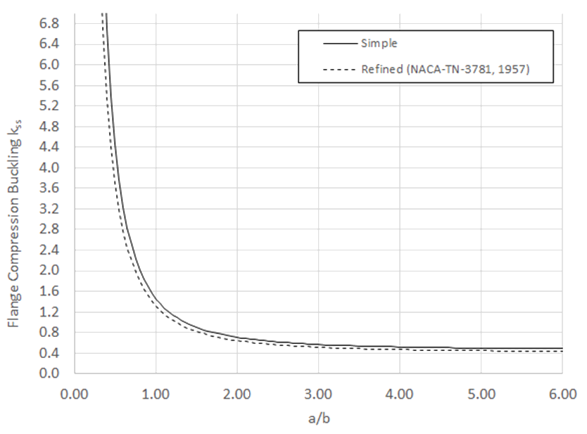
Comparison of the simple expressions for a simply supported flange and the general expression per (![]() NACA-Report-734) equation B-17 is shown on the following figure:
NACA-Report-734) equation B-17 is shown on the following figure:
The flange compression buckling coefficients for a simply supported edge is calculated in the spreadsheet at the link below:
The refined simple method gives, presumably, a more accurate and conservative approach that is asymptotic to .407. This approximation will be used.
The simple approach to flange compression buckling is given in this spreadsheet:
Using this simple approach if Fcr exceeds Fcy then limit Fcr to Fcy .
A spreadsheet for the simple flange buckling method is available at the link below:
The modification for the buckling analysis is the same approach as defined for compression panel in section 15.2.4.3. The change in k for flange buckling for differing levels of edge restraint is shown below:
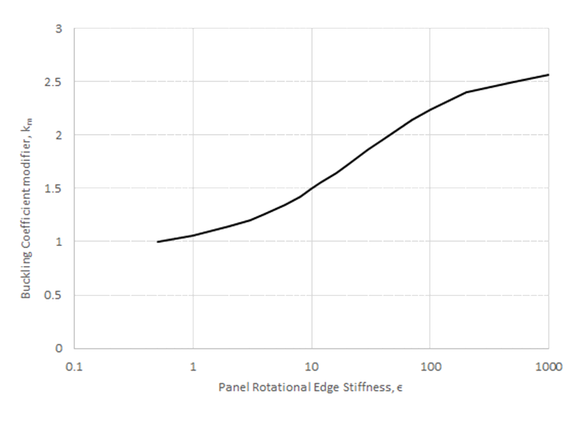
A spreadsheet for the flange buckling method for varying amounts of edge rotational restraint is available at the link below:
15.2.6.2. Flange Compression Buckling Allowable Stress with Full Elasto-Plastic Material Data
If the calculated flange compression buckling stress is approaching the compression yield stress (Fcy) of the material the elastic flange compression buckling allowable could be optimistic. If a more nuanced approach than limiting the buckling stress to Fcy is required, the compression buckling allowable should be modified using the plasticity correction factor η.
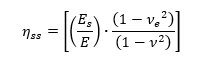
From (![]() NACA-TN-3781, 1957) for compression buckling the plasticity correction factor for a simply supported flange is:
NACA-TN-3781, 1957) for compression buckling the plasticity correction factor for a simply supported flange is:
the plasticity correction factor for a long, clamped flange is:
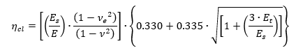
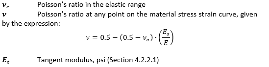
Where:

Plotting these two plasticity correction factors for a typical aluminum gives the following result:
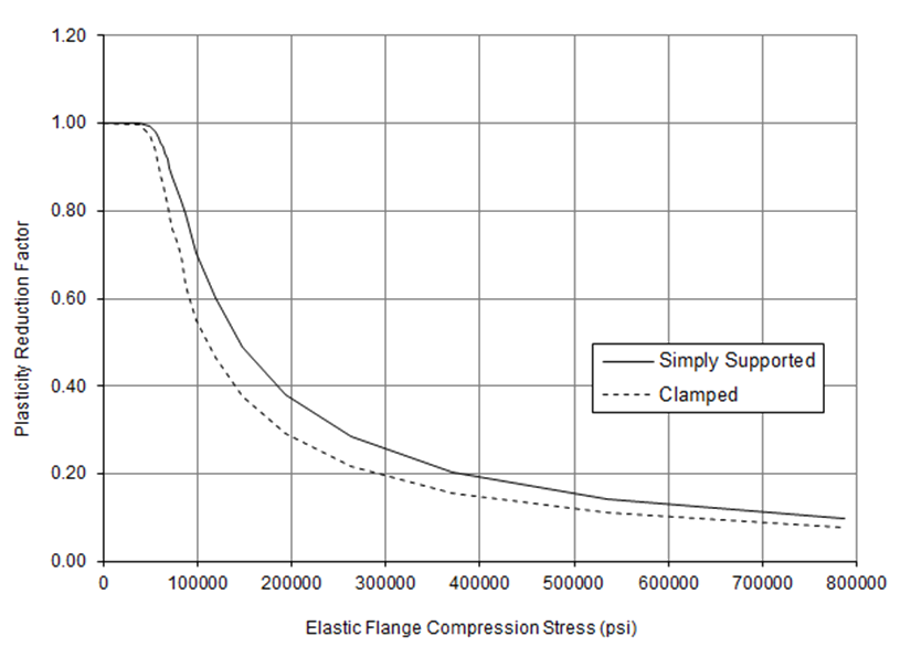
This shows that the reduction factor for a clamped flange is greater that for a simply supported flange. It is recommended that the plasticity reduction factor for the clamped flange is used for all edge conditions.
Superimposing the simpler approach of limiting Fcr to Fcy over the Elastic vs Plastic shear buckling stress curve for a clamped flange gives the following result:
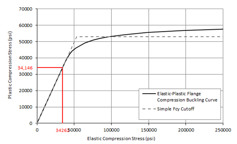
Similar to shear and compression buckling for panels, for the sample material (and for most ductile materials) the simple approach does give a reasonable approximation to the correctly calculated flange plastic buckling allowable.
A spreadsheet for flange buckling that incorporates varying edge rotational restraint and elasto-plastic material behavior is available at the link below: