15.2.2.1. Introduction
The fundamental purpose of cored laminate is to achieve a disproportionate increase in out-of-plane stiffness when compared to the weight increase. This particular increase in property makes cored panels more resistant to panel buckling effects.
Panel buckling is just one of a set of stability failure modes that cored laminates can experience. The critical failure mode depends on the type of core (honeycomb or foam), the thickness and material properties of the core, the material and thickness of the face sheets and the overall panel dimensions.
The failure modes that will be covered in this section are:
Global Mode: (Panel) Buckling
 NASA/CR-1999-208994, 1999)
 Global Mode: Shear Crimping
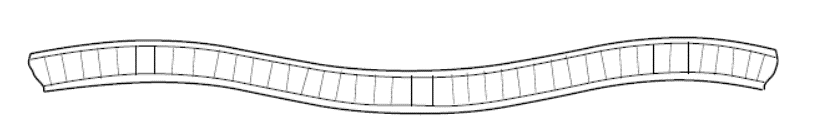
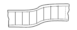
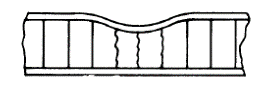
Shear crimping appears to be a local mode of failure but is actually a form of general overall buckling in which the wavelength of the buckles is very small because of low core shear modulus. The crimping of the sandwich occurs suddenly and usually causes the core to fail in shear at the crimp. It may also cause shear failure in the bond between the facing and core.
 NASA/CR-1999-208994, 1999)
 Crimping may also occur in cases where the overall buckle begins to appear and then the crimp occurs suddenly because of severe local shear stresses at the ends of the overall buckle. As soon as the crimp appears, the overall buckle may disappear. Therefore, although examination of the failed sandwich indicates crimping or shear instability, failure may have begun by overall buckling that finally caused crimping.
Local Mode: Facesheet Dimpling
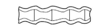
If the core is of cellular (honeycomb) or corrugated material, it is possible for the facings to buckle or dimple into the spaces between core walls or corrugations as shown below:
 NASA/CR-1999-208994, 1999)
 Dimpling may be severe enough so that the amplitude of the dimples may be large enough to cause the dimples to grow across the core cell walls and result in a wrinkling of the facings.
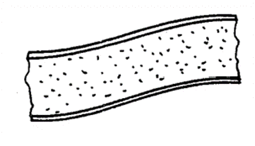
Local Mode: Facesheet Wrinkling
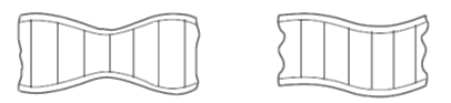
Wrinkling may occur if a sandwich facing subjected to edgewise compression buckles as a panel on an elastic foundation. The facing may buckle inward or outward, depending on the flatwise compressive strength of the core relative to the flatwise tensile strength of the bond between the facing and core. If the bond between facing and core is strong, facings can wrinkle and cause tension failure in the core. Thus, the wrinkling load depends upon the elasticity and strength of the foundation system; namely, the core and the bond between facing and core. Since the facing is never perfectly flat, the wrinkling load will also depend upon the initial eccentricity of the facing or original waviness.
 NASA/CR-1999-208994, 1999)
 Other Local Failure modes:
 NASA CR-1457, 1969)
 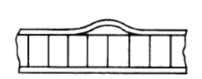 NASA CR-1457, 1969)
 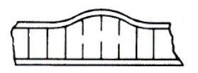 NASA CR-1457, 1969)
 Note:
It is important to note that all of these failure modes can result in catastrophic global failure of the panel. A sandwich panel is dependent on the cohesion of the face sheets and the core and the local failure modes can initiate global failure modes. Because of the out-of-plane stiffness of the sandwich panel, the secondary loads generated by the buckling failure modes are often significant and catastrophic.
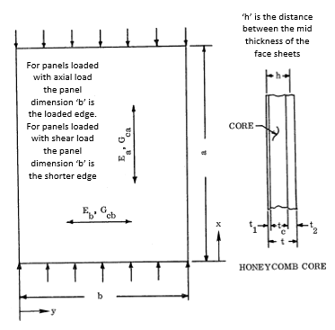
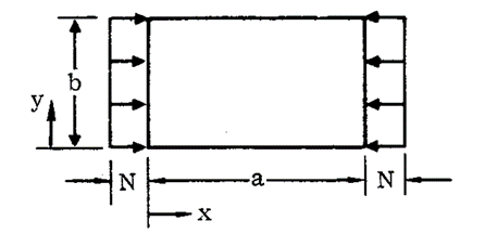
General Panel Nomenclature:
 NASA CR-1457, 1969)
 16.2.2.2. Global Mode: Panel Buckling
The panel buckling methods are taken from (![]() NASA CR-1457, 1969). This reference gives solutions for orthotropic and isotropic facings. Much of the work on buckling of sandwich panels, and the work on sandwich panels in general, originate in the US Forest Product Laboratory reports and their pioneering work done in the 1950s and 1960s. We have collected the relevant reports and host them on our website, they can be found here.
NASA CR-1457, 1969). This reference gives solutions for orthotropic and isotropic facings. Much of the work on buckling of sandwich panels, and the work on sandwich panels in general, originate in the US Forest Product Laboratory reports and their pioneering work done in the 1950s and 1960s. We have collected the relevant reports and host them on our website, they can be found here.
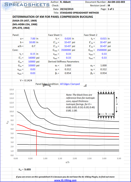
16.2.2.3. Sandwich Panel Compression Buckling
 NASA CR-1457, 1969)
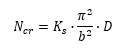
 The load per unit panel width at which buckling of a sandwich panel will occur is given by the theoretical formula:
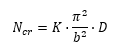
Where Ncr is the allowable load flow (lb/in).
The D11 term from the D matrix of the laminate can be used for ‘D’ in the expression above.
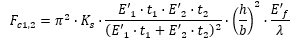
Solved for face sheet stresses:
For sandwich panels with equal face sheets:
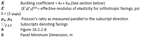
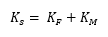
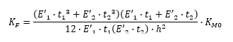
As noted above the buckling coefficient for the panel under this loading condition is given by the equation:
Where:
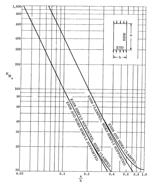
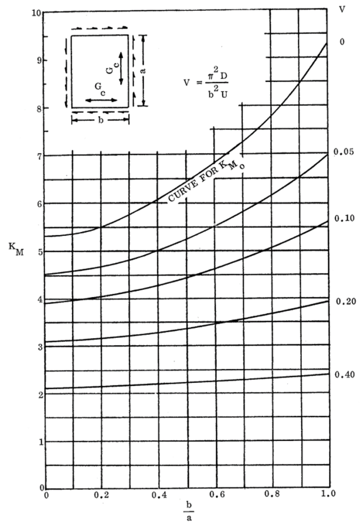
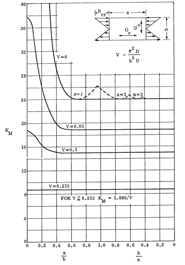
KM0 is given by the following figure:
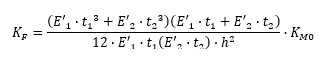
 NASA CR-1457, 1969)
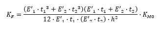
 The values of KF are generally small relative to KM. As safe first approximation is to assume KF is equal to zero unless the margin of safety is low.
For sizing it is safe to assume K = KM.
KM0 = KM when V = 0, see definition of V below, and when a/b > 1.0 it can be assumed KF = 0.
The value of KM is related to the bending shear rigidity parameter V:
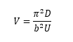
Where
U = Sandwich transverse shears stiffness, defined as:
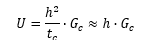
V can also be defined in terms of the geometry and properties of the face sheets and core:
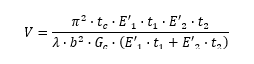
Where:
Having the necessary physical properties of the panel defined, the K value and the buckling allowable can be derived.
The basic cored panel physical properties can be calculated using this spreadsheet:
Derivation of KM for cored panels in compression
(![]() FPL-070, 1964) gives a mathematical derivation of compression buckling coefficients for cored panels. The full derivation will not be given in this text but the math is implemented in the spreadsheet below. The curves for KM have been developed using this reference and reference curves for isotropic core for α= 1.00, β= 1.00 and γ = 0.375 are given in this spreadsheet:
FPL-070, 1964) gives a mathematical derivation of compression buckling coefficients for cored panels. The full derivation will not be given in this text but the math is implemented in the spreadsheet below. The curves for KM have been developed using this reference and reference curves for isotropic core for α= 1.00, β= 1.00 and γ = 0.375 are given in this spreadsheet:
The reference curves for cored panel compression buckling from
(![]() NASA CR-1457, 1969) are shown below. The general solution, mathematically derived per (
NASA CR-1457, 1969) are shown below. The general solution, mathematically derived per (![]() FPL-070, 1964) for all panels is given in the following spreadsheet:
FPL-070, 1964) for all panels is given in the following spreadsheet:
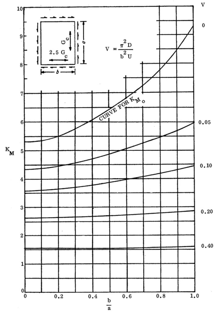
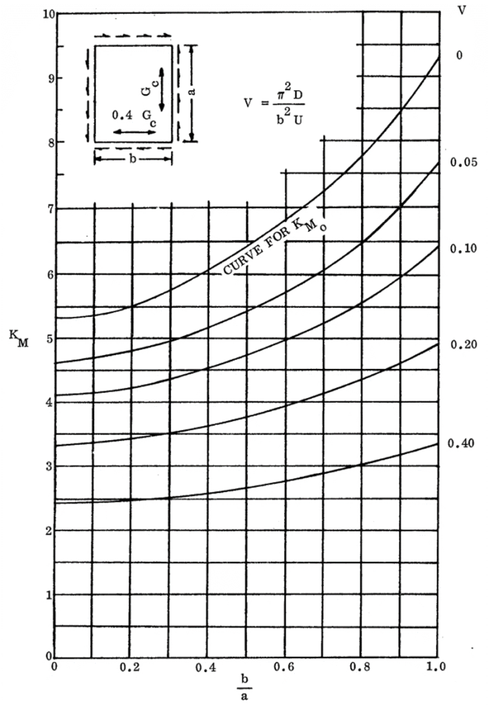
The sandwich panel compression buckling coefficient figures are given below, it is recommended that the spreadsheet method is used to determine the compression buckling coefficient. The following figures should be used for comparison and checking.
In the following figures the term ‘R’ is used, this is the degree of core shear modulus orthotropicity (Gca/Gcb).
16.2.2.4. Sandwich Panel Compression Buckling Coefficients for Panels with Isotropic Facings and Isotropic Core
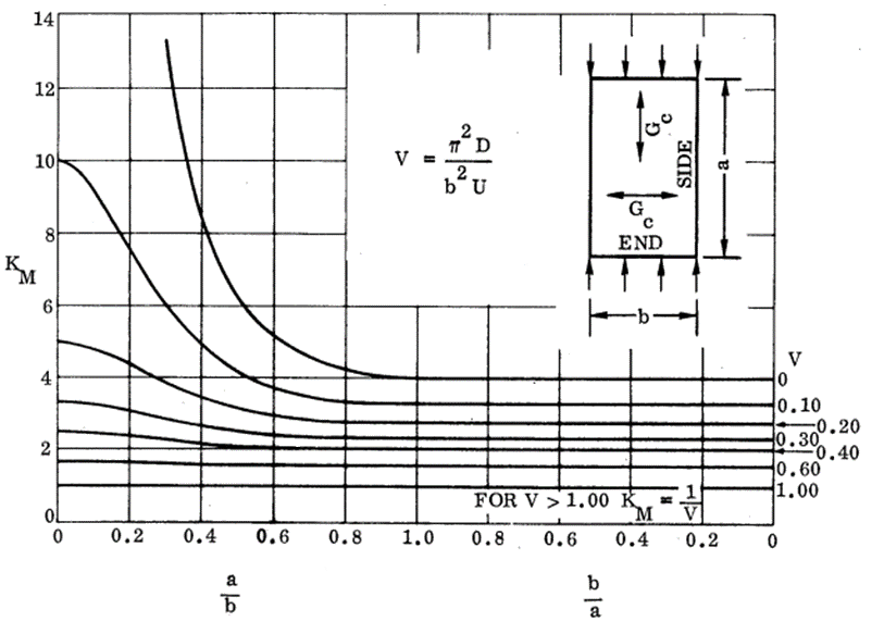 NASA CR-1457, 1969)
 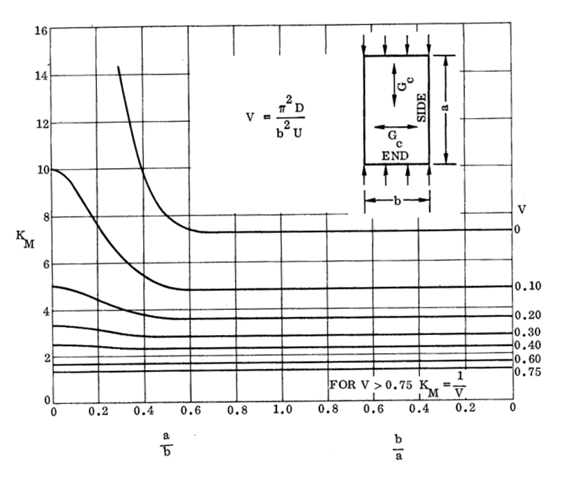 NASA CR-1457, 1969)
 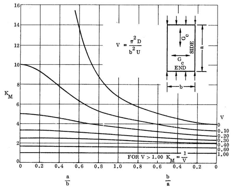 NASA CR-1457, 1969)
 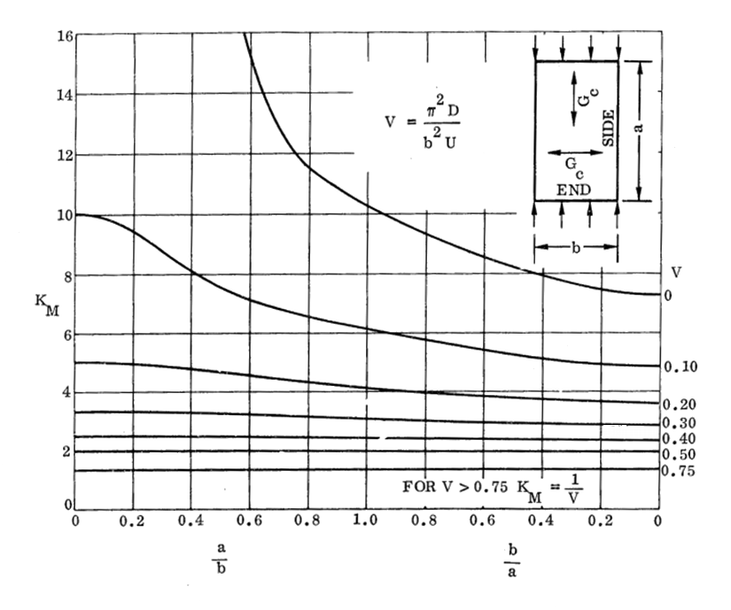 NASA CR-1457, 1969)
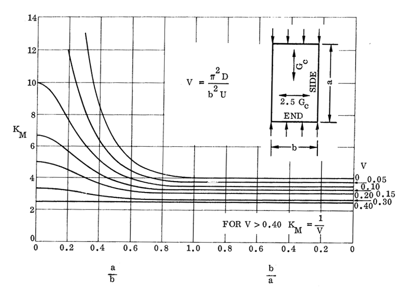
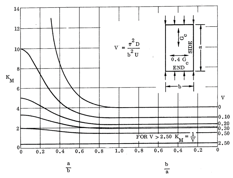
 16.2.2.5. Sandwich Panel Compression Buckling Coefficients for Panels with Isotropic Facings and Orthotropic Core (R=0.40):
 NASA CR-1457, 1969)
 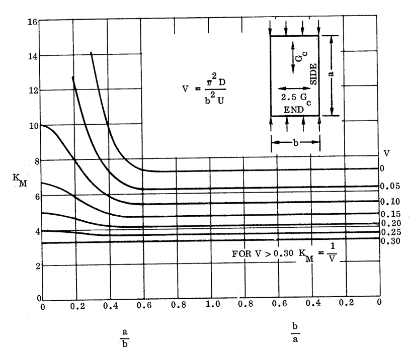 NASA CR-1457, 1969)
 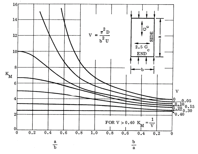 NASA CR-1457, 1969)
 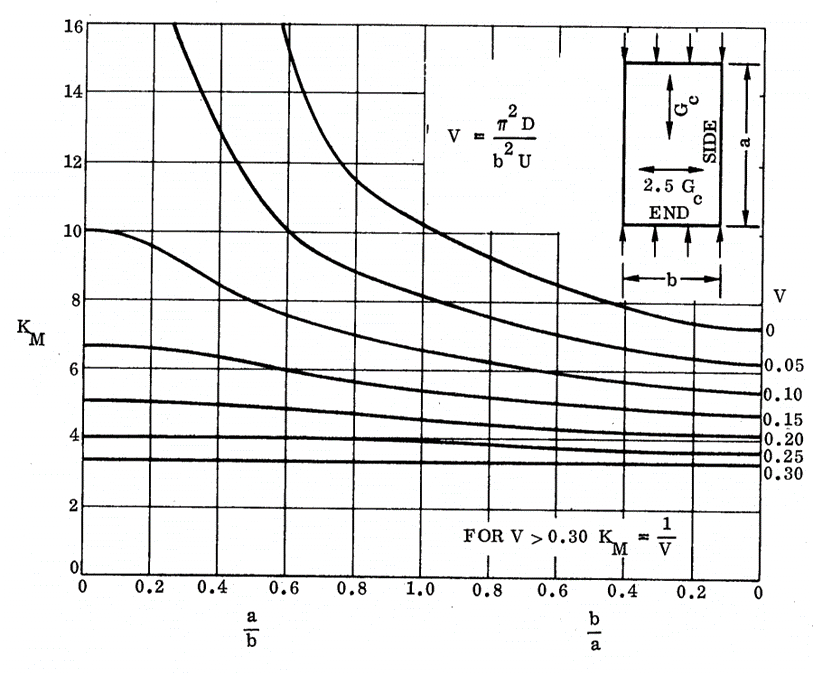 NASA CR-1457, 1969)
 16.2.2.6. Sandwich Panel Compression Buckling Coefficients for Panels with Isotropic Facings and Orthotropic Core (R=2.50):
 NASA CR-1457, 1969)
 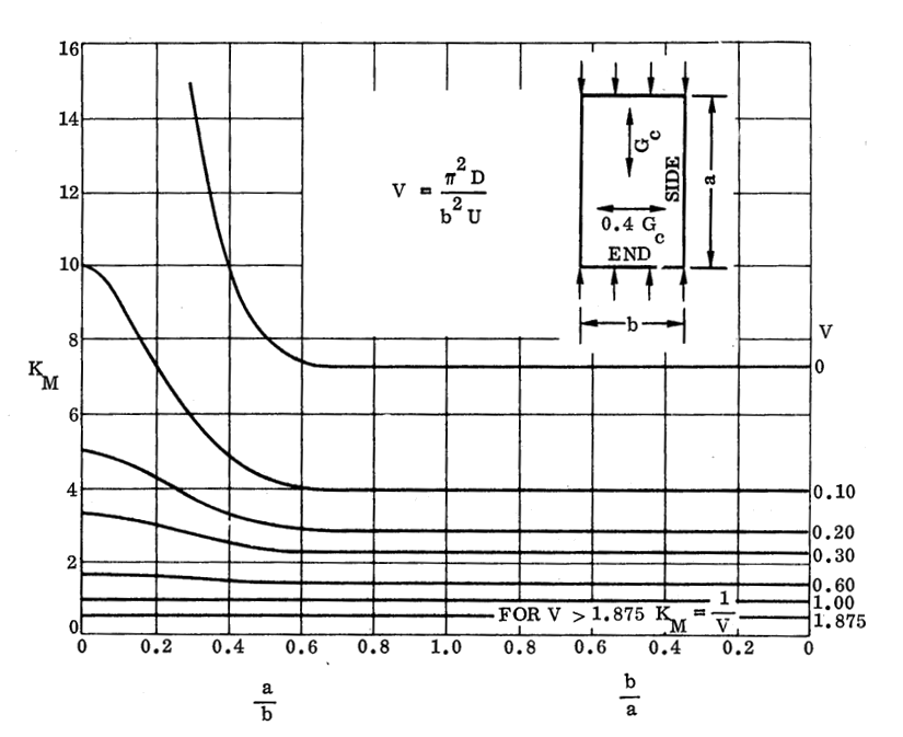 NASA CR-1457, 1969)
 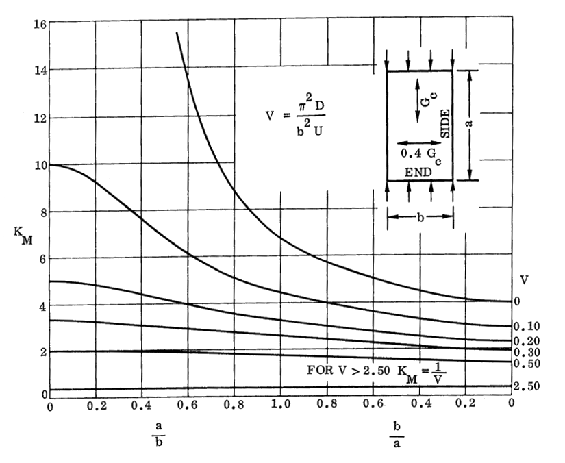 NASA CR-1457, 1969)
 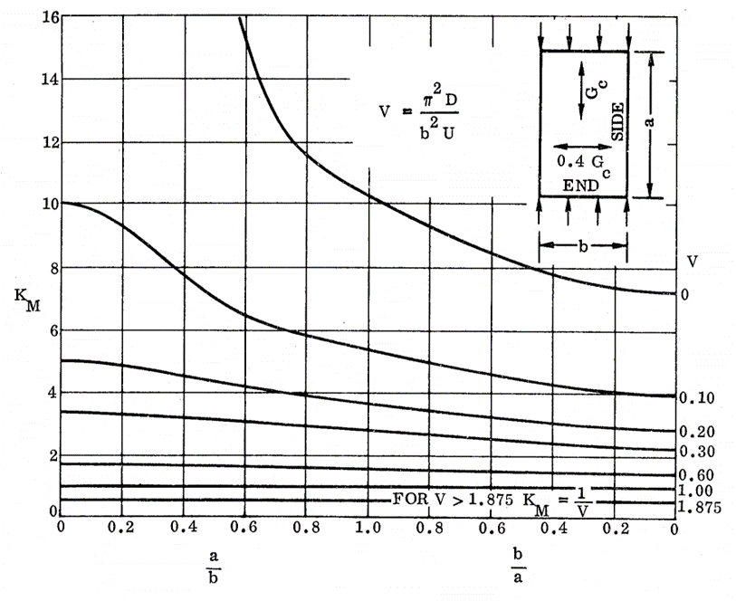 NASA CR-1457, 1969)
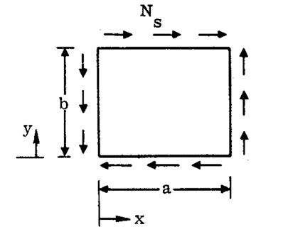
 16.2.2.7. Sandwich Panel Shear Buckling
 NASA CR-1457, 1969)
 The base theory for the expression for buckling is the same as defined for the compression buckle in section 16.2.2.3.
The load per unit panel width at which shear buckling of a sandwich panel will occur is given by the theoretical formula:
Where: Ncr is the allowable load flow (lb/in).
The D11 term from the D matrix of the laminate can be used.
Solved for face sheet stresses:
For isotropic face sheets this formula solved for the facing stress becomes:
Where:
As noted above the buckling coefficient for the panel under this loading condition is given by the equation:
Where:
And:
KMO= KFM when V= 0 – This is the upper line from each of the curves.
As for compression buckling of cored panels, the values of KF are generally small relative to KM. As safe first approximation is to assume it is equal to zero unless the margin of safety is low.
For sizing it is safe to assume K = KM, however for greater accuracy KF can be calculated by taking the KM0 values from the curves on the following pages.
16.2.2.8. Sandwich Panel Shear Buckling Coefficients for Panels with Isotropic Facings and Isotropic Core:
 NASA CR-1457, 1969) NASA CR-1457, 1969)
 16.2.2.9. Sandwich Panel Shear Buckling Coefficients for Panels with Isotropic Facings and Orthotropic Core (R=0.40):
 NASA CR-1457, 1969)
 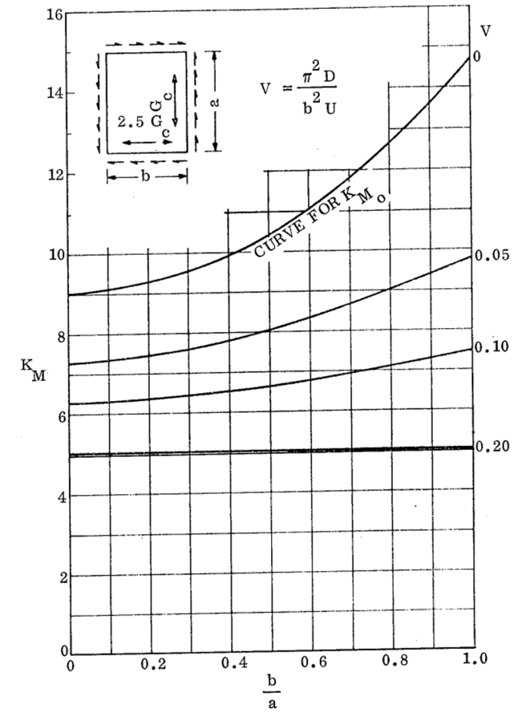 NASA CR-1457, 1969)
 16.2.2.10. Sandwich Panel Shear Buckling Coefficients for Panels with Isotropic Facings and Orthotropic Core (R=2.50):
 NASA CR-1457, 1969)
 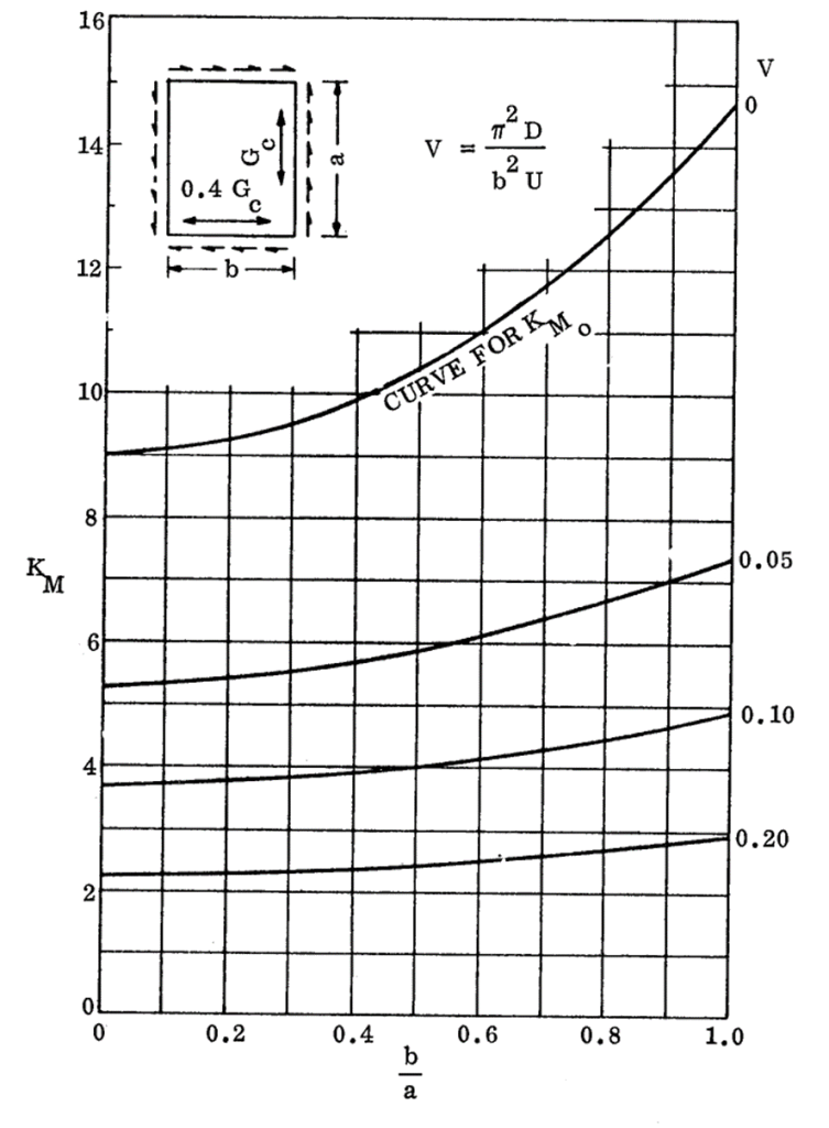 NASA CR-1457, 1969)
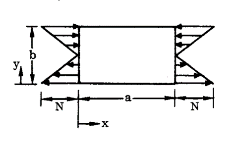
 16.2.2.11. Sandwich Panel Bending Buckling
An in-plane bending load applied to a panel is generally less critical than the same panel in compression as the panel is stabilized by the half of the panel that is loaded in tension.
 NASA CR-1457, 1969)
 The load per unit panel width at which bending buckling of a sandwich panel will occur is given by the theoretical formula:
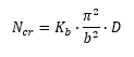
Where: Ncr is the allowable load flow (lb/in).
The D11 term from the D matrix of the laminate can be used.
Solved for face sheet stresses:
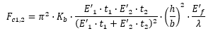
For isotropic face sheets this formula solved for the facing stress becomes:
Where:
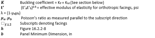
As noted above the buckling coefficient for the panel under this loading condition is given by the equation:
Where:
And:
KMO= KM when V= 0 – This is the upper line from each of the curves.
16.2.2.12. Sandwich Panel Shear Buckling Coefficients for Panels with Isotropic Facings:
 NASA CR-1457, 1969)
 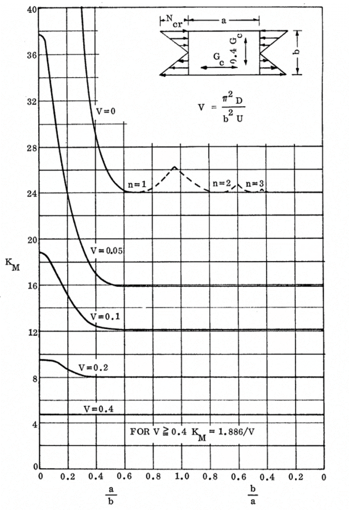 NASA CR-1457, 1969) NASA CR-1457, 1969)
 16.2.2.13. Combined Loading Conditions for Sandwich Panels
The reference (![]() NASA CR-1457, 1969) states that these interaction methods are for honeycomb cored panel. These methods can be assumed to apply for panels with isotropic cores.
NASA CR-1457, 1969) states that these interaction methods are for honeycomb cored panel. These methods can be assumed to apply for panels with isotropic cores.
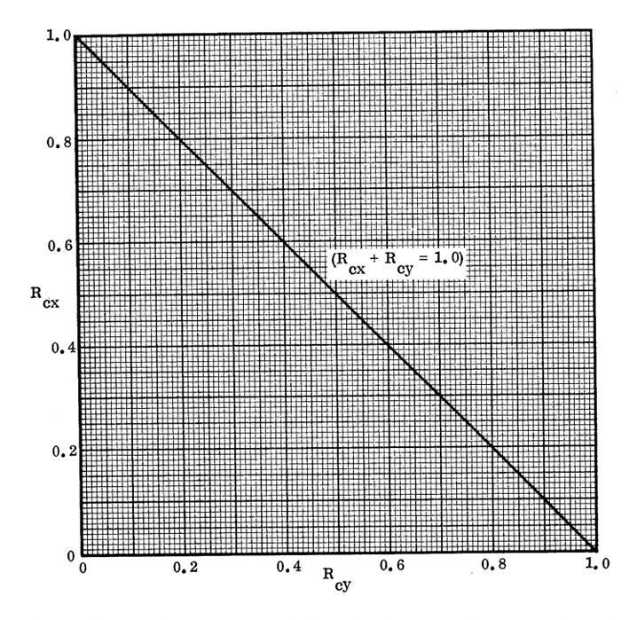
Biaxial Compression:
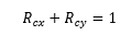
Where:

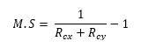
This method is correct for square panels for which V=0, it is generally conservative for panels with larger aspect ratios and larger values of V (weaker core).
 NASA CR-1457, 1969)
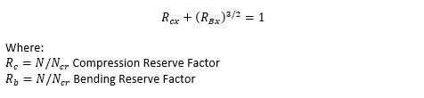
 Bending and Compression:
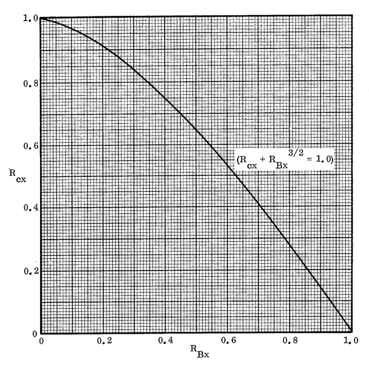 NASA CR-1457, 1969)
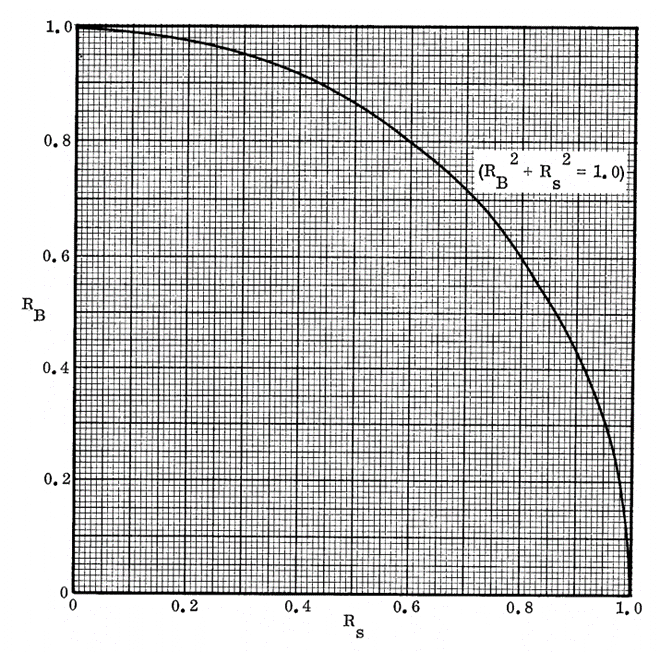
 Compression and Shear:
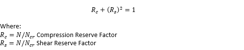
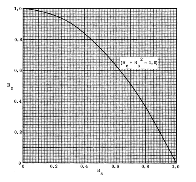 NASA CR-1457, 1969)
 Bending and Shear:
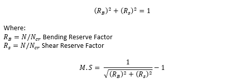
 NASA CR-1457, 1969)
 All of these interaction effects are available in the spreadsheet linked below:
16.2.2.14. Global Mode: Shear Crimping
The shear crimping mode of failure can occur because of insufficient shear stiffness of the core.
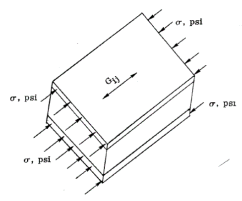
For uniaxial compression acting co-planar with the facings:
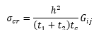
Where Gij is the core shear modulus of the plane perpendicular to the face sheets and parallel to the direction of loading.
 NASA CR-1457, 1969)
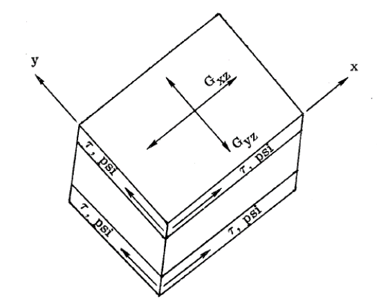
 For pure shear acting co-planar with the facings:
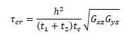
Where Gxz and Gyz are the core shear moduli of the plane perpendicular to the face sheets (z) and parallel to the direction of loading (x,y).
 NASA CR-1457, 1969)
 This method is available in the following spreadsheet:
16.2.2.15. Local Mode: Facesheet Dimpling (Intracellular Buckling)
From a practical viewpoint intracellular buckling can be regarded as flat Panel behavior. Even where curvature is present, as in the cases of cylinders and spheres, the honeycomb core size will usually be sufficiently small to justify such an assumption.
As noted from (![]() NACA-TN-3781, 1957), the critical stress for flat Panels can be expressed in the form (note that this is for isotropic face sheets).
NACA-TN-3781, 1957), the critical stress for flat Panels can be expressed in the form (note that this is for isotropic face sheets).
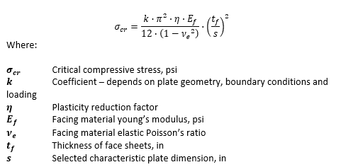
For elastic cases and composite face sheets it can be assumed that η = 1.
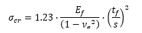
(![]() NASA CR-1457, 1969) recommends that a K value of 2.0 is used. However, it is noted that this value has been shown to be optimistic in some cases. A review of the experimental data shows that this may be particularly optimistic for honeycomb core. It is therefore recommended that a K value of 1.5 is used.
NASA CR-1457, 1969) recommends that a K value of 2.0 is used. However, it is noted that this value has been shown to be optimistic in some cases. A review of the experimental data shows that this may be particularly optimistic for honeycomb core. It is therefore recommended that a K value of 1.5 is used.
The dimension ‘s’ is related to the cell size of the core. The recommended value of s is determined as follows:
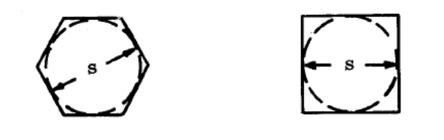 NASA CR-1457, 1969)
 The term for intracellular buckling therefore becomes:
This method is available in the following spreadsheet:
16.2.2.16. Local Mode: Facesheet Wrinkling
Antisymmetric Wrinkling: Typical facesheet wrinkling failure mode in solid/foam cores (![]() NASA CR-1457, 1969).
NASA CR-1457, 1969).
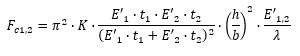
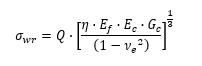
The stress in the face sheet at which face wrinkling will occur in sandwich constructions having solid or foam cores is given by:
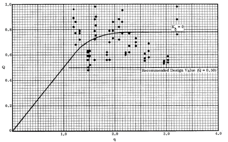
(![]() NASA CR-1457, 1969) gives guidance that in the absence of any other information the value of Q can be conservatively assumed to be 0.50. This is based on the results shown below.
NASA CR-1457, 1969) gives guidance that in the absence of any other information the value of Q can be conservatively assumed to be 0.50. This is based on the results shown below.
For elastic cases it can be assumed that η = 1, in almost all cases for composite laminate face sheets they must remain elastic and therefore η = 1.
 NASA CR-1457, 1969)
 The precise value of Q can be calculated of the amplitude of the initial waviness in the facings is known. This is expanded on and explained in (![]() NASA CR-1457, 1969).
NASA CR-1457, 1969).
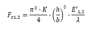
It is recommended that unless the user has significant experience with this subject that a Q of 0.5 is used. Therefore, the expression becomes:
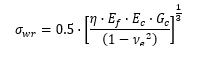
For elastic cases and composite face sheets it can be assumed that η = 1. It is noted in the source material that this method is approximate and therefore should be used for initial sizing only.
Symmetric Wrinkling: Typical facesheet wrinkling failure mode in honeycomb cores only (![]() NASA CR-1457, 1969).
NASA CR-1457, 1969).
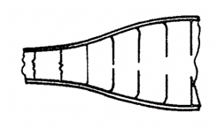
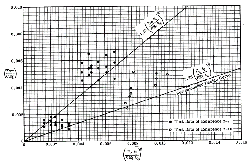
For unknown initial waviness and for preliminary design use the following expression:
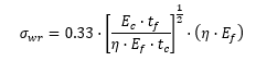
For elastic cases and composite face sheets it can be assumed that η = 1. It is noted in the source material that this method is approximate and conservative and therefore should be used for initial sizing only.
 NASA CR-1457, 1969)
 This method is available in the following spreadsheet: