The methods below are taken from (![]() MIL-HDBK-17F Vol 3, 2002) Section 5.7 and (
MIL-HDBK-17F Vol 3, 2002) Section 5.7 and (![]() NASA-TN-D-7996, 1975). The following caveats apply to the applicability of this analysis method:
NASA-TN-D-7996, 1975). The following caveats apply to the applicability of this analysis method:
……. the closed form solutions of laminated orthotropic Panels are appropriate only when the lay-ups are symmetrical and balanced. Symmetrical implies identical corresponding plies about the Panel mid-surface. Balanced refers to having a minus _ ply for every plus _ ply on each side of the mid-surface. Symmetrical and balanced laminated Panels have B terms vanish and the D16 and D26 terms virtually vanish…….
Note that the buckling performance of a panel depends on the panel size, the rigidity of the panel edge constraints and the out-of-plane stiffness of the panel. The out-of-plane stiffness of the panel is expressed using the D matrix component of the laminate ABD matrix, see section 4.1.6.1 of this document for more information.
Note that these methods are not specifically limited to uncored laminates but the effect of the presence of core on the buckling solution can be significant depending on the characteristics of the core panel.
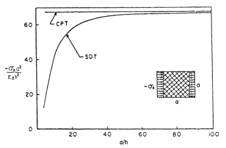
Classical Panel theory is based up on the Kirchhoff hypothesis: “Normals to the mid-plane of the un-deformed Panel remain straight and normal to the mid-plane during deformation”. This assumption therefore ignores the transverse shear deformation. Consideration of the shear deformation results in added flexibility which becomes significant as the Panel thickness increases relative to the length and width. (![]() AFWAL-TR-85-3069, 1985)
AFWAL-TR-85-3069, 1985)
 AFWAL-TR-85-3069, 1985)
 However, there are buckling predictions specifically for cored laminate panels and these are examined in section 16.2.2 of this document.
It is recommended that the analyst uses multiple methods, if they are available, so the results can be compared and correlated. It is also useful when the opportunity comes to test structures that have been designed using these methods as the test results can be used to help select the ‘best fit’ analysis for future work.
Notes:
All of the following methods are for large aspect ratio panels. Note that for short aspect ratio panels these solutions will give conservative results.
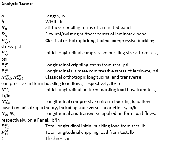
These methods correlate well with test for b/t ratios greater than 35 – see figure on next page:
 MIL-HDBK-17F Vol 3, 2002)
 For b/t ratios lower than 35, the Ncrx,I / Ncrx,cl ratio shows that the following methods will be significantly optimistic.
For this method to be accurate for a laminate panel of 0.040in thickness the b dimension would have to be greater than 0.040 x 35 = 1.4in.
This correlates to the difference in the predicted buckling performance between methods that account for transverse shear and those that do not, as shown in Figure 16.2.1‑1. The inaccuracy in this methodology is strongly influenced by the out-of-plane shear effect.
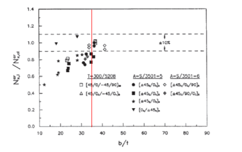
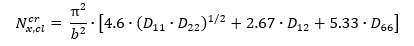
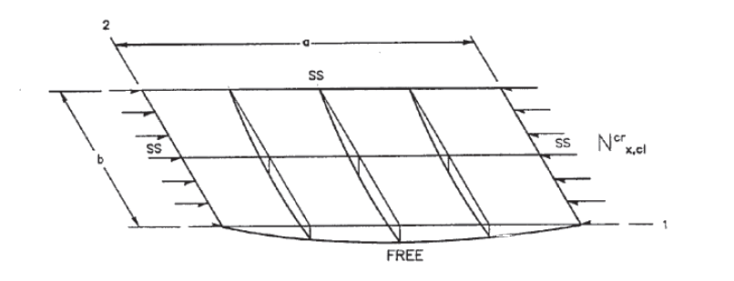
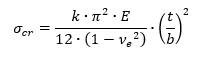
16.2.1.1. Uniaxial Loading, Long Panel, All Sides Simply Supported
(Aspect ratio >4)
For long plates the loaded edges can also be clamped and the allowable buckling stress will not be affected.
 MIL-HDBK-17F Vol 3, 2002)
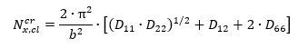
 The end load flow (lb/in) for the point of initial buckling is given by the following expression:
This method is available in the following spreadsheet:
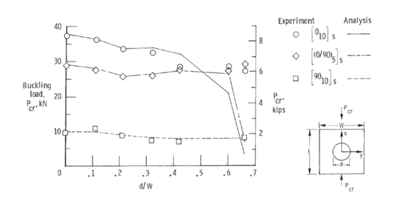
16.2.1.2. Effect of Central Circular Hole on Simply Supported Compression Buckling Allowable (![]() NASA-TP-2528, 1986):
NASA-TP-2528, 1986):
An approximate solution for the effect of a circular hole on the compression buckling performance of a square panel is given by the following method. This method is defined by the reduction in K, the compression buckling coefficient. The value of K for the panel without a hole can be generated from the calculated compression buckling allowable using the following expression:
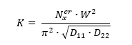
Where W is the width of the loaded edge of the panel – ‘b’ in standard nomenclature.
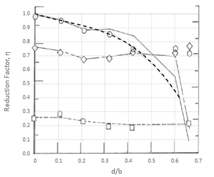
The effect on the compression buckling allowable for a simply supported Panel is given by this figure:
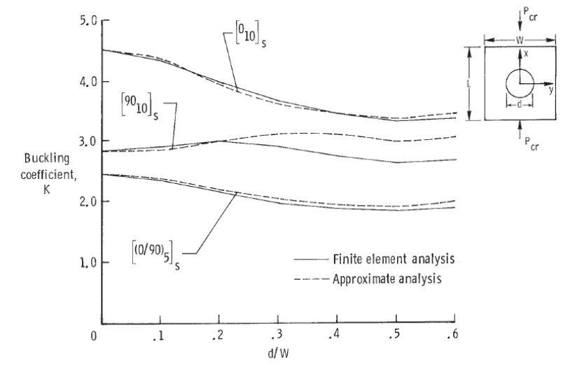 NASA-TP-2528, 1986)
 The graph shows various results for different methods. The greatest overall reduction in K from all the curves will be used to generate a reduction factor that can be used to modify the K value or the compression buckling allowable directly.
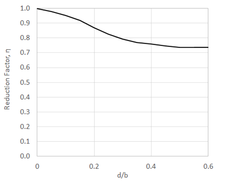
This is expressed in the following figure:
(note that this reduction factor graph is in broad agreement with
(![]() AFWAL-TR-85-3069, 1985) Figure 7.2.
AFWAL-TR-85-3069, 1985) Figure 7.2.
The end load flow for the point of initial buckling for a panel with a central circular hole becomes:
This method is available in the following spreadsheet:
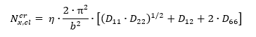
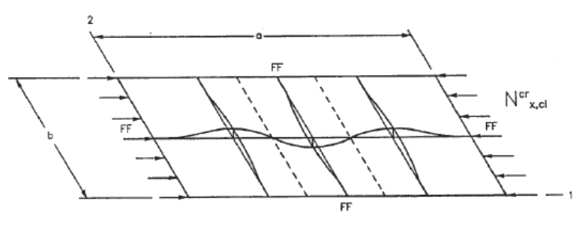
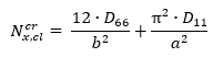
16.2.1.3. Uniaxial Loading, long Panel, all sides Fixed
(Aspect ratio >4)
 MIL-HDBK-17F Vol 3, 2002)
 The end load flow for the point of initial buckling is given by this expression:
This method is available in the following spreadsheet:
16.2.1.4. Effect of Central Circular Hole on Fully Fixed Compression Buckling Allowable
An approximate solution for the effect of a circular hole on the compression buckling performance of a square panel with fully fixed edges is given by the following method:
The effect on the compression buckling allowable for a fully fixed Panel is given by this figure:
 NASA-TP-2528, 1986)
 The graph shows various results for different methods. It is recommended that the trace showing the greatest reduction is used. As there are a range of results comparing analysis and test methods, a conservative approximation over the critical data sets has been used with a cubic line of best fit:
The end load flow for the point of initial buckling for a panel with a central circular hole becomes:
This method is available in the following spreadsheet.
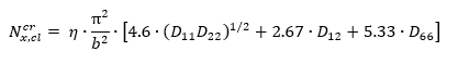
16.2.1.5. Uniaxial Loading, Long Panel, Three Sides Simply Supported and One Unloaded Edge Free
 MIL-HDBK-17F Vol 3, 2002)
 The end load flow for the point of initial buckling:
This method is available in the following spreadsheet:
The following methods for shear buckling are more refined and give solutions for finite length panels covering a range of panel aspect ratios.
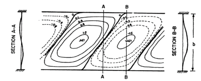
16.2.1.6. Shear Loading, Panel with all sides simply supported
 AFWAL-TR-85-3069, 1985)
 The shear buckling analysis method is taken from (![]() NASA-TN-D-7996, 1975) which gives buckling solutions for shear and compression combinations. This paper gives the basic solution for shear buckling of a finite panel so we have used this as the best available reference. The general solution of the shear buckling equations can be expressed using the following parameter:
NASA-TN-D-7996, 1975) which gives buckling solutions for shear and compression combinations. This paper gives the basic solution for shear buckling of a finite panel so we have used this as the best available reference. The general solution of the shear buckling equations can be expressed using the following parameter:
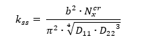
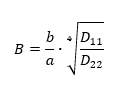
The parameter ks is a function of only two variables:
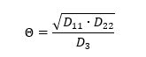
Where: D3 = D12 + 2D66
And:
To find the ks for panel with simply supported edges see Figure 16.2.1‑11:
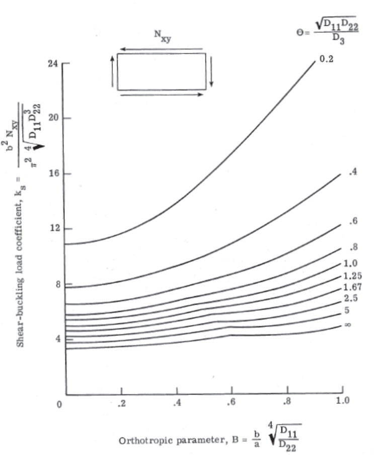 NASA-TN-D-7996, 1975)
 Therefore:
This method is available in the following spreadsheet:
To find the ks for panel with fully fixed edges see Figure 16.2.1‑12:
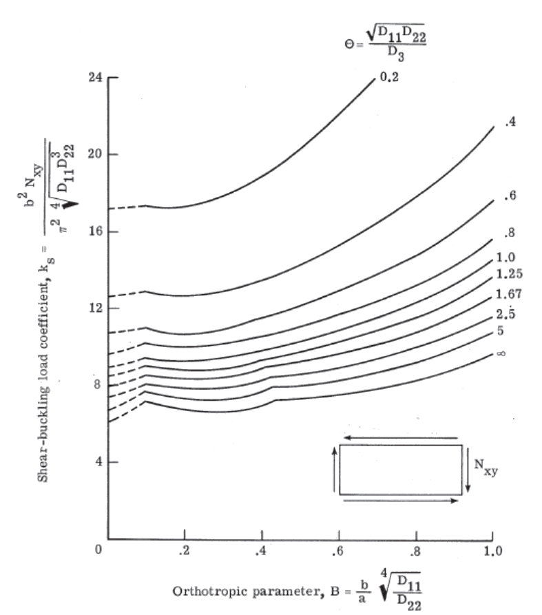 NASA-TN-D-7996, 1975)
 For a panel with edges fixed in rotation the spreadsheet method is available here:
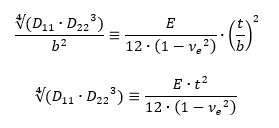
Once Ks has been found graphically the equation for ks can easily be rearranged to give the solution for Nxy:
Note that this equation is a similar form to the buckling equation for isotropic Panel buckling from (![]() NACA-TN-3781, 1957), shown in its general form below:
NACA-TN-3781, 1957), shown in its general form below:
The equivalent terms that express the out-of-plane stiffness of the Panel are:
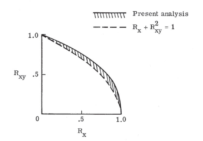
16.2.1.7. Interaction of Compression and Shear Buckling Effects
Ref (![]() NASA-TN-D-7996, 1975) shows comparison between a set of analyses and a linear/squared interaction. This demonstrates that using the mathematical approximation of the compression buckling reserve factor and the square of the shear buckling reserve factor is conservative.
NASA-TN-D-7996, 1975) shows comparison between a set of analyses and a linear/squared interaction. This demonstrates that using the mathematical approximation of the compression buckling reserve factor and the square of the shear buckling reserve factor is conservative.
This approach is confirmed in (![]() NASA CR-2330, 1974).
NASA CR-2330, 1974).
 NASA-TN-D-7996, 1975)
 This interaction method is available as a spreadsheet solution here:
16.2.1.8. Note on Post-Buckling and Crippling
As noted at the start of this chapter it is common to keep composite structure non-buckling up to ultimate load. Post buckling effects will not be covered in this edition. Crippling is a post buckling failure mode thus it will not be covered.
It is recommended that all composite primary structure be kept non-buckling up to ultimate load.