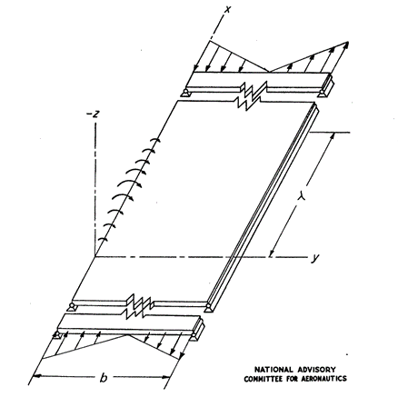
 NACA-TN-1323, 1947)
 The simplest approach to panel bending buckling and the approach that is commonly used for initial sizing is to assume that η =1 and the panel is simply supported.
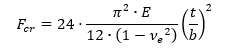
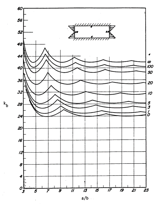
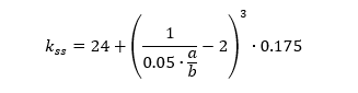
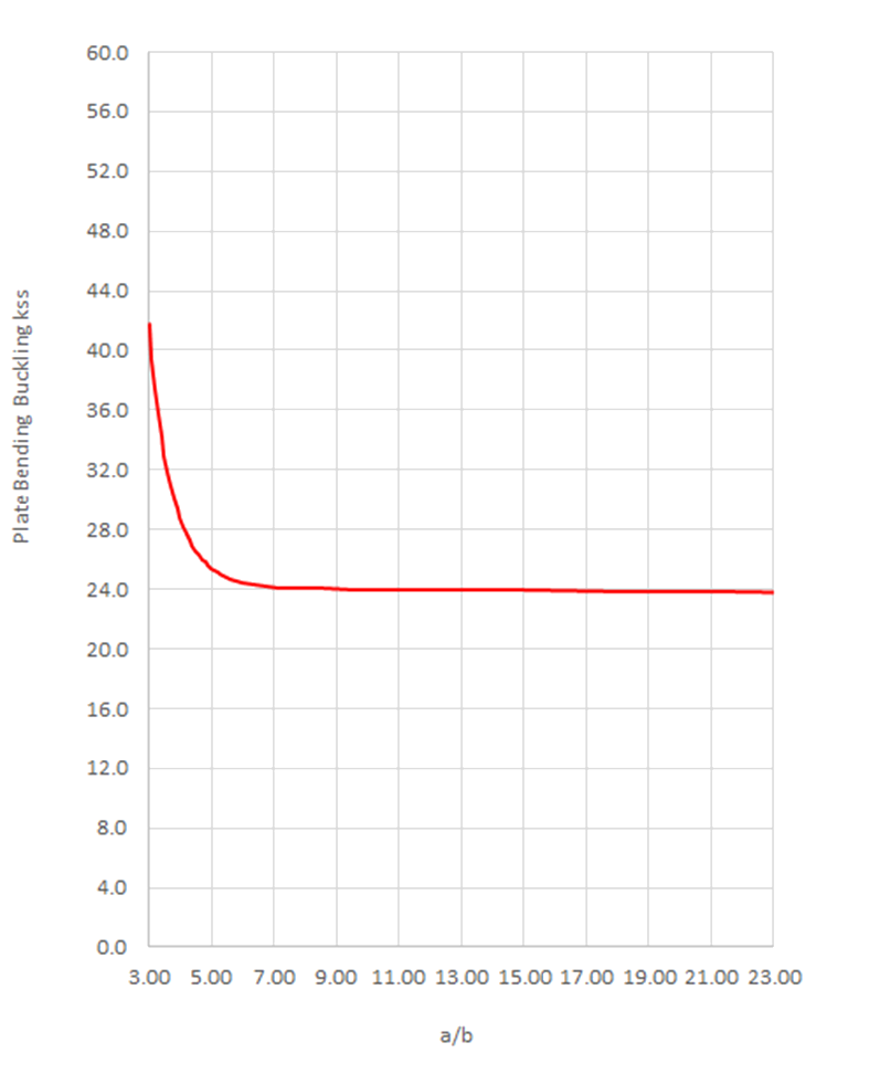
The kss for a panel of infinite length can be assumed to be 24 (Ref Figure 15.2.7‑2). Therefore, for a simple first check the following expression can be used.
In general, the buckling ‘k’ value for panel bending buckling is approximately 6 times the panel compression buckling coefficient. The k value is given by the figure below:
 AFFDL-TR-69-42, 1986)
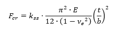
 The bending buckling coefficient for a simply supported Panel can be approximated by the following expression:
The flange compression buckling coefficients for a simply supported edge is shown in the spreadsheet:
The simple approach to panel bending buckling is given in this spreadsheet:
Using this simple approach if Fcr exceeds Fcy then limit Fcr to Fcy.
15.2.7.1. Bending Buckling Allowable Stress with Varying Panel Rotational Edge Fixity
The effect of differing levels of edge restraint on the buckling allowable is proportionally the same as that shown in Figure 15.2.4‑6 and section 15.2.4.3 for the compression panel. This relationship will be adapted for bending buckling. This approach is given in a spreadsheet form at the link below:
15.2.7.2. Bending Buckling Allowable Stress with Full Elasto-Plastic Material Data
The plasticity reduction factor for panels in bending buckling can be assumed to be the same as for the flange compression buckling allowable as recommended in (![]() NACA-TN-3781, 1957). These plasticity reduction factors are defined in section 15.2.6.2. The spreadsheet for this method is given at the link below:
NACA-TN-3781, 1957). These plasticity reduction factors are defined in section 15.2.6.2. The spreadsheet for this method is given at the link below: