12.2.11.1. Beam in a Socket Analysis
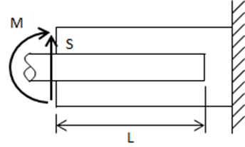
A beam in a socket type analysis is usually applicable for cantilevered (single shear) pins in fittings. The nature of these joints means that the engagement length of the pin in the ‘socket’ is usually some multiple of the pin diameter. This is required to reduce the peak bearing load between the pin and the socket to an acceptable level.
The method is predicated on a continuous contact between the pin and the socket and a uniform bearing load distribution between the pin and the socket. This method is referenced to R. Burandt in 1959, and an expanded method (that gives essentially the same results) is defined in (![]() NASA-CR-4608, 1994). This method was provided to me by Bosko Zdanski in October 2013.
NASA-CR-4608, 1994). This method was provided to me by Bosko Zdanski in October 2013.
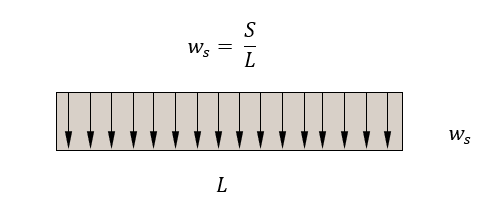
Distributed socket reaction to shear load:
Moment at Socket Center:
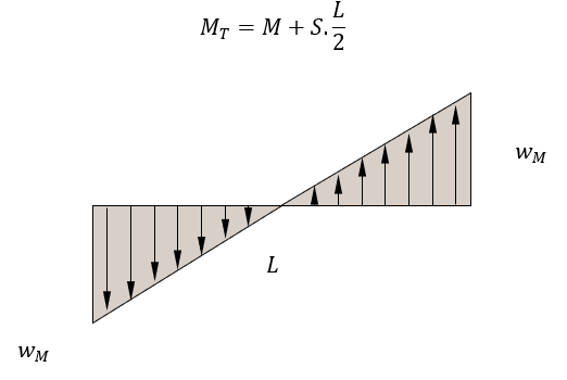
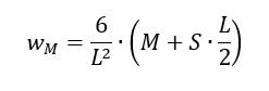
Distributed socket reaction to Moment Load at Socket Center:
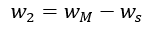
Socket Reaction at Outer End:
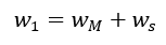
This expands to:
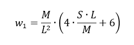
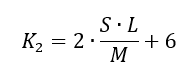
Introducing:
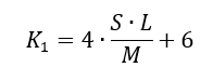
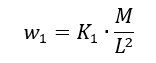
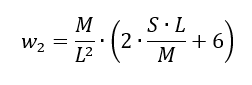
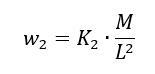
The resulting expression is:
Socket reaction at bottom end:
This expands to:
Introducing:
The resulting expression is:
From a linear load distribution, it follows that:
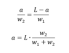
Introducing:
The resulting expression is:

Where ‘a’ is the distance from the ‘bottom’ of the socket to the point of zero shear load:
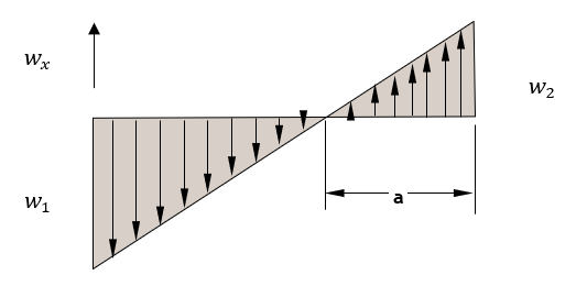
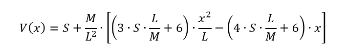
Local distributed reaction along socket is given by:
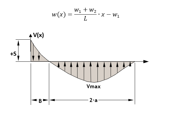
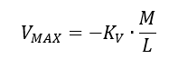
Pin maximum shear load:
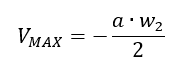
Introducing:
The resulting expression is:
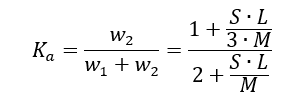
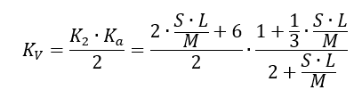
The point of pin zero shear load is given by:
Introducing:
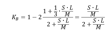
The resulting expression is:
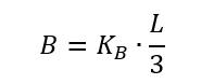
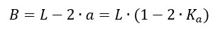
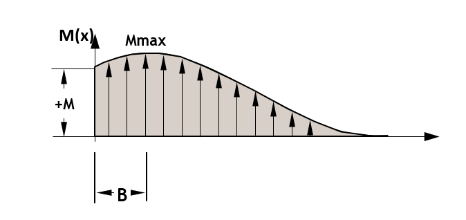
The location ‘B’ is also where the maximum pin internal moment occurs.
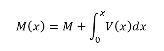
The expression for the pin internal shear load is:
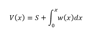
This can be expanded to:
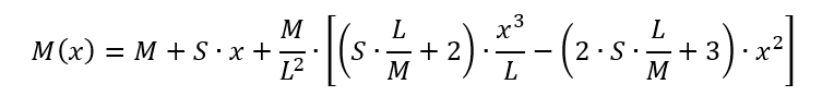
The expression for the pin internal shear Moment is:
This can be expanded to:
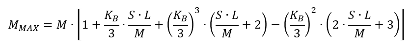
The maximum pin moment occurs at point ‘B’ coincidental with the point of zero internal pin shear:
This method is available in our standard spreadsheet format here: