12.2.10.1. Pin Bending
The pin used in the lug joint should be checked for pin bending. To obtain the effective moment arm of the pin compute the following for the inner lug:
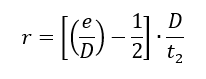
Where e, D and t2 are the lug edge distance, hole/pin diameter and thickness respectively defined in Figure 12.2.9‑2.
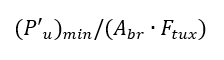
Take the smaller of P’bru and P’tu for the inner lug as (P’u)min and compute the following expression:
Obtain the reduction factor ‘γ’ from the following figure:
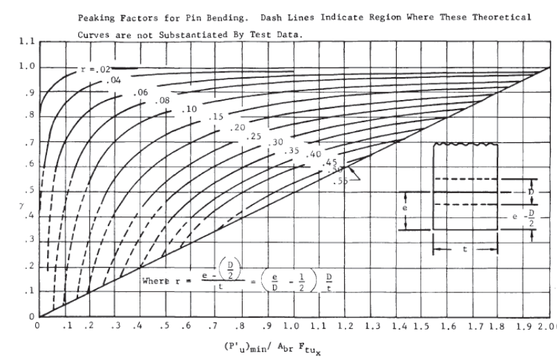
 NASA TM X-73305, 1975)
 The effective moment arm can then be calculated using the following expression:
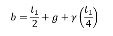
Where the terms in the expression are defined in the figure below:
 NASA TM X-73305, 1975)
 Calculate pin bending moment from the equation:
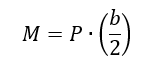
Calculate the bending stress resulting from “M” assuming the standard My/I distribution.
The resulting bending stress can be compared to the pin plastic bending allowable.
Note: A fitting factor per the regulations of at least 1.15 should be used. Some OEMs require a minimum margin of safety of 0.25 for lugs, or an effective fitting factor of 1.25.
A spreadsheet for this method is available at the link below:
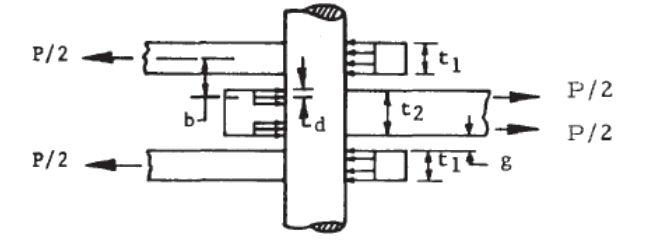
12.2.10.2 Stresses due to Press Fit Bushings
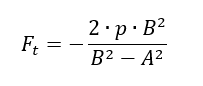
The method in this section is referenced to (![]() AFFDL-TR-69-42, 1986) Section 9.16. Note that several errors in the source material have been corrected. The expression for the maximum tangential stress for the bushing: The ‘p’ and ‘B’ should be in regular font, therefore the numerator becomes ‘2pB2’ and the denominator of this expression should read ‘B2-A2’.
AFFDL-TR-69-42, 1986) Section 9.16. Note that several errors in the source material have been corrected. The expression for the maximum tangential stress for the bushing: The ‘p’ and ‘B’ should be in regular font, therefore the numerator becomes ‘2pB2’ and the denominator of this expression should read ‘B2-A2’.
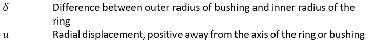
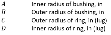
The pressure between a lug and a bushing assembly having negative clearance can be determined by consideration of the radial displacements. This method assumes the lug acts as if it is a uniform ring around the bushing. After assembly, the increase in the inner radius of the ring (lug), plus the decrease in the outer radius of the bushing equals the difference between the radii of the bushing and ring (lug) before assembly.
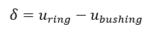
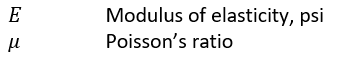
Where:
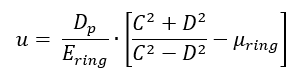
Radial displacement at the inner surface of a ring subjected to internal pressure p is:
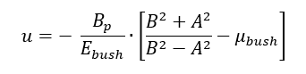
Radial displacement at the outer surface of a bushing subjected to external pressure p is:
Where:
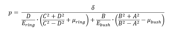
Combining these equations and substituting into the first equation and solving for p gives the following expression:
Maximum radial and tangential stresses for a ring (lug) subjected to internal pressure occur at the inner surface of the ring (lug).
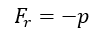
Maximum radial stress for lug (the pressure on the interface between the lug and the bushing):
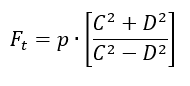
Maximum tangential stress for lug:
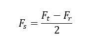
Positive sign indicates tension. The maximum shear stress at this point in the lug is:
The maximum radial stress for a bushing subjected to external pressure occurs at the outer surface of the bushing and is:
The maximum tangential stress for a bushing subjected to external pressure occurs at the inner surface of the bushing and is:
Acceptable stress levels:
- Stress corrosion. This maximum allowable press fit stress in magnesium alloys should not exceed 8000psi. For all aluminum alloys, the maximum press fit stress should not exceed 0.50Fty.
- Static fatigue. For steels heat treated to above 200ksi, where there is any risk of hydrogen embrittlement the press fit stress should not exceed 0.25Ftu.
- Ultimate strength. Ftu should not be exceeded. However, it is rare to create stresses of this magnitude in a press fit bushing installation.
A spreadsheet for this method is available at the link below: