Most of this section can be cited to (![]() NASA TM X-73305, 1975) although the method in the quoted reference is essentially the same as the original 1953 lug analysis paper by Melcon and Hoblit.
NASA TM X-73305, 1975) although the method in the quoted reference is essentially the same as the original 1953 lug analysis paper by Melcon and Hoblit.
- A lug can be described as a ‘single bolt fitting’ – typically used to transmit large loads and provide a joint that can quickly be disconnected.
- In a typical bolted joint, the hole created by the presence of the bolt does not play a significant role in the overall strength of the joint – i.e. the net section strength of the sheet item is not significantly less than the gross strength of the sheet, and in any case the tension strength of the sheet is typically not the critical measure of strength in a typical bolted joint. However, in a lug the bolt hole has a significant effect on the strength of the joint.
Lug Load Nomenclature:
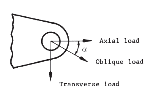
It is recommended that for all lug analyses a 10% off axis load effect is considered combined with the major load direction. This gives allowance for misalignment on installation and the effect of deflection under load of the wider structural assembly.
The lug can fail in any of the following failure modes:
- Tension across the net section
- Shear tear out or bearing
- Shear of the pin
- Bending of the pin
- Side load on the lug (checked by conventional beam method)
Lug dimension nomenclature:
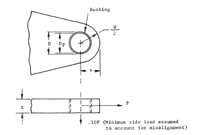
Derived Lug dimensional terms:
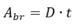
Bearing Area:
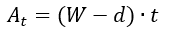
Net Tension Area:
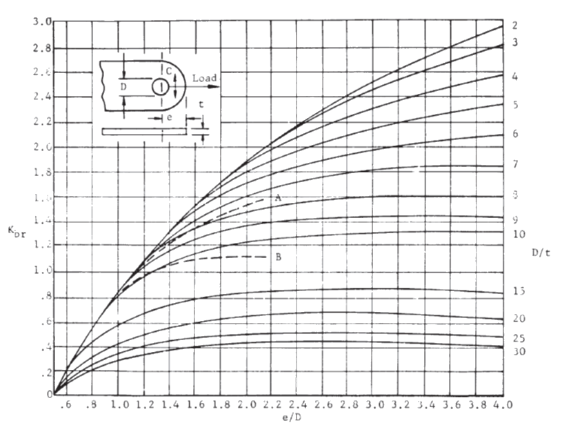
12.2.9.1. Shear Tear-Out or Bearing Failure
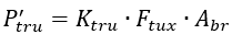
The ultimate allowable load for shear bearing failure:
Where:
Ftux = Ultimate tensile strength of lug material in the transverse direction.
Kbr is taken from the following figure:
 NASA TM X-73305, 1975)
 A spreadsheet for this method is available at the link below:
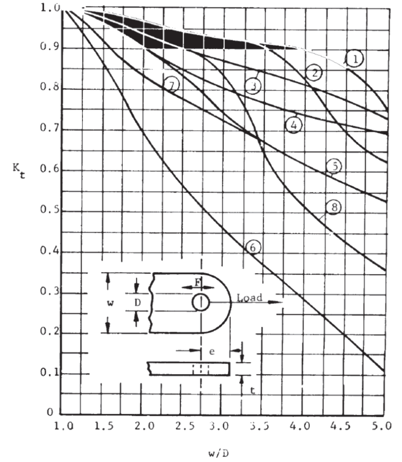
12.2.9.2. Tension Across the Net Section
The ultimate allowable for tension failure:
Where:
Ftu = Ultimate tensile strength of lug material.
Kt is taken from the following figure:
 NASA TM X-73305, 1975)
 Notes for Figure 12.2.9‑4:
L = longitudinal, T = long transverse, N = short transverse (normal)
Curve 1:
4130, 4140, 4340 and 8630 steel
2014-T6 and 7075-T6 Panel ≤ 0.5 in (L,T)
7075-T6 bar and extrusion (L)
2014-T6 hand forged billet ≤ 144 sq. in. (L)
2014-T6 and 7075-T6 die forgings (L)
Curve 2:
2014-T6 and 7075-T6 Panel > 0.5 in., _ 1 in.
7075-T6 extrusion (T,N)
7075-T6 hand forged billet ≤ 36 sq.in. (L)
2014-T6 hand forged billet > 144 sq.in. (L)
2014-T6 hand forged billet ≤ 36 sq.in. (T)
2014-T6 and 7075-T6 die forgings (T)
17-4 PH, 17-7 PH-THD
Curve 3:
2024-T6 Panel (L,T)
2024-T4 and 2024-T42 extrusion (L,T,N)
Curve 4:
2024-T4 Panel (L,T), 2024-T3 Panel (L,T)
2014-T6 and 7075-T6 Panel > I in.(L,T)
2024-T4 bar (L,T)
7075-T6 hand forged billet > 36 sq.in. (L)
7075-T6 hand forged billet ≤ 16 sq.in. (T)
Curve 5:
195T6, 220T4, and 356T6 aluminum alloy casting
7075-T6 hand forged billet > 16 sq.in. (T)
2014-T6 hand forged billet > 36 sq.in. (T)
Curve 6:
Aluminum alloy panel, bar, hand forged billet, and die forging (N). Note: for die forgings, N direction exists only at the parting plane. 7075-T6 bar (T)
Curve 7:
18-8 stainless steel, annealed
Curve 8:
18-8 stainless steel, full hard, Note: for 1/4, 1/2 and 3/4
hard, interpolate between Curves 7 and 8.
A spreadsheet for this method is available at the link below:
12.2.9.3. Transverse Lug Strength
The ultimate allowable for transverse failure:
The transverse strength of the lug depends on the shape parameter of the lug. This parameter is expressed as:
Shape parameter =

Where:
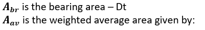
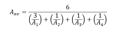
The areas A1, A2, A3 and A4 are defined as:
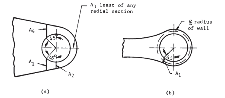 NASA TM X-73305, 1975)
 A3 is the least area on any radial section around the hole.
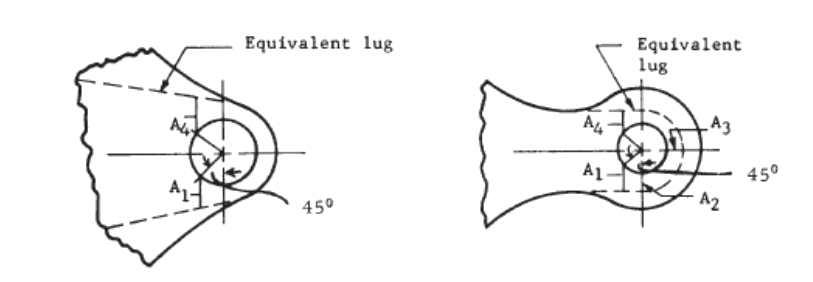
Thought should always be given to assure that the areas A1, A2, A3 and A4 adequately reflect the strength of the lug. For lugs with an unusual shape or a sudden change in cross section a conservative equivalent lug should as assumed.
 NASA TM X-73305, 1975)
 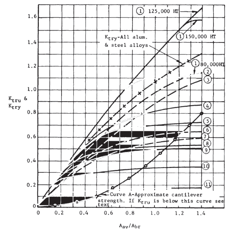 NASA TM X-73305, 1975)
 Notes for Figure 12.2.9‑7:
Curve 1:
4130, 4140, 4340, and 8630 steels, heat treatment as noted. – Curve (a) for 125Ksi HT, Curve (b) for 150Ksi HT, Curve (c) for 80Ksi HT
Curve 2:
2024-T4 and 2024-T3 Panel ≤ 0.5 in.
Curve 3:
220-T4 aluminum alloy casting
Curve 4 :
17-7 PH (THD)
Curve 5 :
2014-T6 and 7075-T6 Panel ≤ 0.5 in.
Curve 6:
2024-T3 and 2024-T4 Panel >0.5 in., 2024-T4 bar
Curve 7:
195-T6 and 356-T6 aluminum alloy casting
Curve 8:
2014-T6 and 7075-T6 Panel>0.5 in.,≤1 in.
7075-T6 extrusion
2014-T6 hand forged billets ≤ 36 sq. in.
2014-T6 and 7075-T6 die forgings
Curve 9:
2024-T6 Panel
2024-T4 and 2024-T42 extrusion
Curve 10:
2014-T6 and 7075-T6 Panel > 1 in.
7075-T6 hand forged billet ≤16 sq. in.
Curve 11:
7075-T6 hand forged billet >16 sq. in.
2014-T6 hand forged billet >36 sq. in.
12.2.9.4. Lugs – Combined Axial and Transverse (Oblique) Load
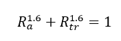
In analyzing a lug, the load applied should be broken into axial and transverse components (denoted by subscripts “a” and “tr” respectively) relative to the idealized lug. The two separate cases should be analyzed and the results combined using the interaction equation:
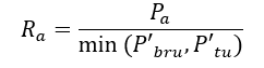
Where:
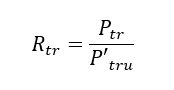
And:
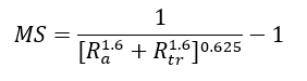
The Margin of Safety is calculated as follows:
A spreadsheet for this method is available at the link below: