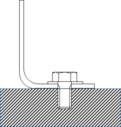
Tension clips are used when it is not possible to transfer load as shear in a fastener. There are two basic types, single angle and double angle.
- Clips are only used when the load is small. Machined tension fittings should be used for applications in the primary load path.
- Thin clips tend to fail in bending of the clip. Thick clips tend to fail the fastener in the base of the clip due to prying action tension.
- Tension fasteners (not rivets) should be used.
- Keep the bolt head as close to the radius as possible.
A tension clip installation has two significant failure modes, failure of the clip in bending and tension failure of the fastener.
12.2.8.1. Tension Clip – Flange Bending Strength Failure
The analytical methods to determine the strength of tension clip installation has been limited to proprietary data. There is a well-known Lockheed stress memo that provides a method for the analyst and in recent years “Aircraft Stress Analysis and Sizing” by Michael Niu has given an analogous analysis method.
In the development of this book both of these methods were examined, and it was determined that the curves in these two methods were not derived by test but were analytically derived.
The derivation of the tension clip strength method is below:
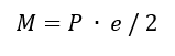
The methodology assumes that the clip is installed onto an effectively rigid foundation, and that the loaded outstanding flange is also restrained in rotation.
Therefore, the clip can be idealized as a simple beam built at the fastener and restrained in rotation at the loaded flange:
The eccentricity of the clip (e) is the length of the idealized beam and P is the load applied at the end restrained in rotation only.
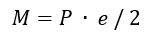
For this arrangement, the critical bending moment occurs at both ends of the beam and is equal to:
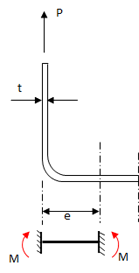
The allowable load is calculated per one inch of angle. The allowable load per fastener is the allowable load from this method multiplied by the fastener pitch.
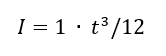
The 2nd moment of area for a unit length of angle flange is equal to:
And the distance from the flange cross section neutral axis to the outer fiber:
Taking the material yield strength Fty, the allowable moment to yield is given by:
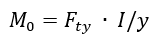
Therefore, the allowable applied load to yield the angle is:
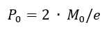
Formed Sheet Aluminum Tension Clips
The allowable load for formed sheet aluminum clips can be found with the following factors:
The factor from yield allowable to ultimate allowable (general minimum for aluminum) is 1.33, the shape factor for a rectangular section is 1.5. The combination of these two factors is 2.00. Therefore, the P0 term above can be multiplied by 2.0 to give an ultimate allowable.
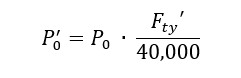
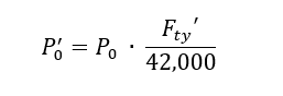
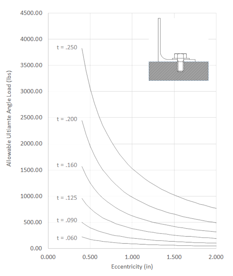
Figure 12.2.8‑2 should be used for formed sheet aluminum with Fty = 40,000psi. The values from this figure can be modified for other grades and tempers of aluminums in the following way:

A spreadsheet for this method is available at the link below:
Extruded Aluminum Tension Clips
The allowable load for extruded aluminum clips can be found with the following factors:
Factor from yield allowable to ultimate allowable (minimum for extruded aluminum) is 1.167, the shape factor for a rectangular section is 1.5. The combination of these two factors is 1.75. The P0 term above can be multiplied by 1.75 to give an ultimate allowable.
Figure 12.2.8‑2 should be used for formed sheet aluminum with Fty = 42,000psi. The values from this figure can be modified for other grades and tempers of aluminum in the following way.
A spreadsheet for this method is available at the link below:
12.2.8.2. Tension Clip – Fastener Tension Failure
The second failure mode of a tension clip installation is a tension failure of the fastener. A fastener tension failure is only likely, for a well-designed joint, by consideration of the heel-toe effect of the fastener location and the edge of the angle flange.
For this load amplification effect to be significant the clip has to have a relatively high bending stiffness. This failure mode is less likely for thinner angles. However, there is no way to determine (other than comprehensive testing) when this effect becomes significant, so it is cautious to check this effect in every case.
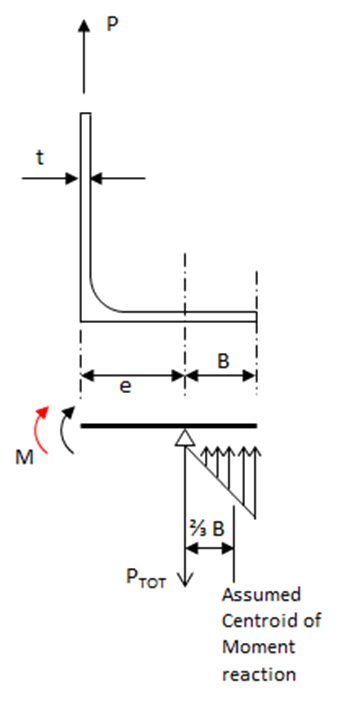
The assumption of how the flange reacts a moment created by the applied load is the same as for the bending check.
The moment reaction at the fastener location is replaced by a couple reaction between the fastener position and an assumed triangular bearing reaction between the underside of the clip and the support structure.
Simplistically, the moment is calculated at the fastener position assuming rotational fixity at the fastener position and the outstanding web. This can be described by the following equation:
The additional force due to the couple reaction is calculated as:
Where 2/3B is the centroid of the assumed triangular reaction force.
The total bolt load is the sum of the applied load and the additional load:

A spreadsheet for this method is available at the link below: