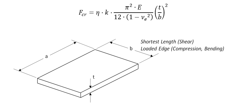
The general buckling equation used for webs and flanges is as shown below:
The expression for web and flange buckling is built around the flexural stiffness of the panel, which can be expressed as:
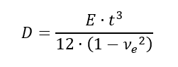
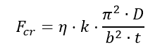
This term is equivalent to D11 from the composite laminate ABD matrix. Expressing the general buckling equation in terms of D, the equation becomes:
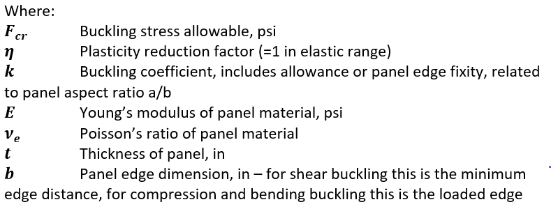
This general equation holds for shear, compression and bending buckling. The ‘k’ value and the meaning of the ‘b’ term changes for each form of buckling.
The value of ‘k’ depends on the level of torsional restraint at the edge of the panel. If it can be considered to act like a hinge – i.e. zero torsional restraint, then the panel is said to be ‘simply supported’, this creates low allowable values. If the edges have a high level of torsional restraint, the edges are said to be ‘clamped’ or ‘built-in’, this creates high allowable values.
Note that all the analysis presented in this section is for symmetrical buckling modes. In almost all cases the symmetrical buckling modes yield lower allowable than the antisymmetric buckling modes. Therefore, the analysis method presented in this section omit anti-symmetric buckling.