Every buckle has a wavelength and in the derivation of buckling allowable values the value λ , the buckle half wave length is an important value. λ is also used later in this section for the calculation of the panel rotational edge fixity.
The value of λ varies depending on the type of loading.
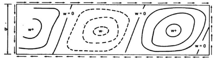
15.2.2.1. Shear Buckle Wavelength
(![]() NACA-TN-2536, 1951) provides some basic data on half wavelengths/panel width for a range of buckling situations. Note that this reference is concerned with the combination of transverse and not axial shear. Therefore, the cases where ks has a non-zero and kb and kc are zero are pure shear.
NACA-TN-2536, 1951) provides some basic data on half wavelengths/panel width for a range of buckling situations. Note that this reference is concerned with the combination of transverse and not axial shear. Therefore, the cases where ks has a non-zero and kb and kc are zero are pure shear.
 NASA TM X-73306, 1975)
 Note that the half wavelength is measured in the panel axial direction and NOT perpendicular to the 45-degree buckle.
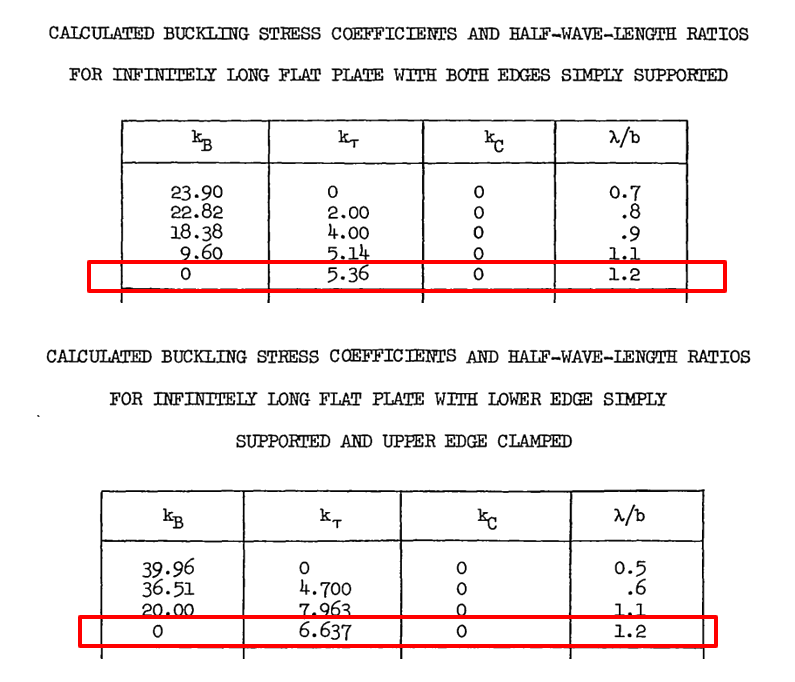 NACA-TN-2536, 1951)
 From this reference, a first approximation for the λ /b ratio can be assumed to be 1.2 for all states of panel rotational edge fixity.
15.2.2.2. Compression Buckle Wavelength
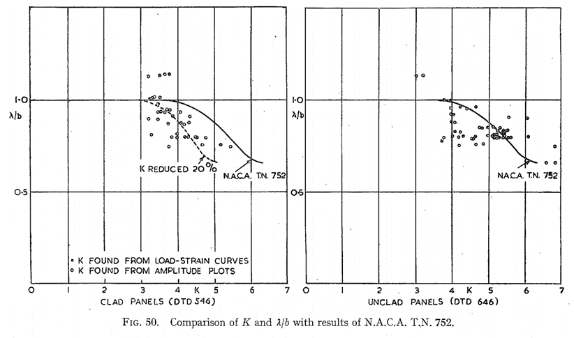
(![]() ARC-RM-2652, 1953) gives a range of good experimental data for compression buckle wavelength:
ARC-RM-2652, 1953) gives a range of good experimental data for compression buckle wavelength:
 ARC-RM-2652, 1953)
 It is noted that the λ /b ratio varies between 0.6 and 1.0.
The wavelength decreases with increasing panel edge rotational fixity.
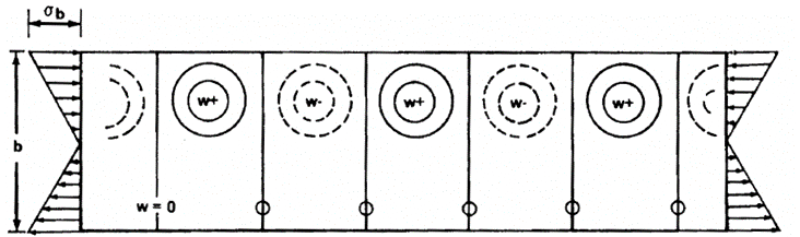
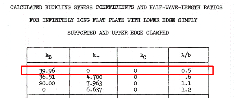
15.2.2.3. Bending Buckle Wavelength
Using the reference for the shear buckle wavelength (![]() NACA-TN-2536, 1951) the wavelength for the bending buckle can be found from the case where ks and kc are equal to zero:
NACA-TN-2536, 1951) the wavelength for the bending buckle can be found from the case where ks and kc are equal to zero:
 NASA TM X-73306, 1975)
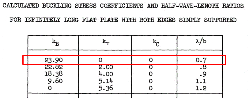
 NACA-TN-2536, 1951)
 For a simply supported panel the λ /b ratio can be assumed to equal 0.70, and for a panel with clamped edges 0.50.
As with the compression buckle the wavelength decreases with increasing panel edge rotational fixity.
These compression, bending and shear buckling wavelengths can be estimated using the following spreadsheet: