In general, it is recommended that for cloth (woven or stitched biaxial reinforcing) ‘quasi-isotropic’ laminates are taken to be the default and that they be as close to balanced and symmetrical as possible. Where both balance and symmetry cannot be achieved simultaneously symmetry should be sacrificed to maintain balance. The effect of an unsymmetrical laminate on outer surface stresses and strains can be calculated and predicted.
Quasi-isotropic laminates are recommended for the following reasons:
- They offer good load resistance in all directions and therefore require no particular effort paid to orientation in manufacturing.
- They offer the best resistance to impact damage and damage growth.
- They produce the best joint strength for mechanical attachments.
- Quasi-isotropic laminates reduce the risk of parts warping when releasing from the mold due to uneven surface strains.
Where high anisotropy (tailored stiffness in a particular orientation) is required – i.e. wing spar caps – local unidirectional fiber (tape) placement is encouraged.
4.1.3.1. Stress-Strain Behavior of Common Composite Laminates
Carbon fiber laminate materials exhibit brittle (non-plastic) failure modes and typically the stress-strain plot remains linear to ultimate failure, see Figure 4.1.3‑1. This behavior is different to typical aircraft metals, see Figure 4.1.3‑2.

Figure 4.1.3‑1: Comparison of Common Laminate Stress-Strain Behavior (Source: Prince Engineering)

Figure 4.1.3‑2: Stress-Strain Data for 2024-T351 ( MIL-HNDBK-5H, 1998)
The linear stress-strain behavior for common composite materials means that ‘Kt’ effects (stress concentrations) that can be ignored at limit and ultimate level analysis (but not for fatigue) in ductile metals must be considered for carbon fiber laminates up to ultimate load level.
The behavior of carbon reinforced epoxy resin laminates also stops any redistribution of load as there is no proportional limit or yield point on the stress-strain curve to exceed. Particular attention must be paid to design; whereas in metals the ultimate strength may rely on load redistribution (plastic joint load redistribution and plastic bending are two examples) carbon fiber laminates do not allow any ‘plastic redistribution’.
Any fiber laminate will exhibit the greatest strength in tension (assuming a reasonable component of 0-degree fibers in the laminate) as tension is carried directly by the fibers, loading the fibers in such a way that they are allowed to develop their ultimate tensile strength.
Fiber laminates show significantly lower strength in compression and shear. In compression, the laminate relies on the resin matrix to support the fibers and maintain their compression stability. The in-plane shear load can be described as a 45degree biaxial compression/tension load and the laminate will generally suffer a compression failure at 45degrees when loaded in shear.
The critical environmental conditions, humidity and temperature affect the resin matrix, not the fibers. This can be seen in the little variation in laminate tension strength for laminates between cold-dry and hot-wet conditions. This is in contrast to the laminate compression and shear strengths which show significant variation with different environmental conditions and a significant reduction for hot and hot wet environmental conditions, this is shown in Figure 4.1.3‑3, Figure 4.1.3‑4 and Figure 4.1.3‑5

Figure 4.1.3‑3: B-Basis Ultimate Tensile Strength, Lamina Strength, Various Environmental Conditions
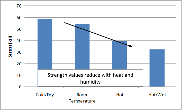
Figure 4.1.3‑4: B-Basis Ultimate Compression Strength, Lamina Strength, Various Environmental Conditions
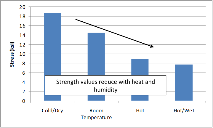
Figure 4.1.3‑5: B-Basis Ultimate Shear Strength, Lamina Strength, Various Environmental Conditions
Because of how the resin matrix reacts to the critical environmental condition (hot-wet) the most common laminate failure modes occur in compression or shear.
Note: Composite laminates are known to be poor in carrying loads perpendicular to the laminate plane – the loading ‘through the thickness’ should be mitigated or minimized at the design stage wherever possible. The out-of-plane load applied directly to laminate can directly drive delamination under relatively modest loads. The severity of this effect is difficult to predict and measure and so should be avoided by design. Where significant out-of-plane loading cannot be avoided, the strength of the feature in question should be determined by testing of the specific feature.
Note: Mating surfaces should be tool/mold surfaces where possible. This allows for greater geometric control over the interface. However, extreme care must be exercised to ensure all bonding surfaces are properly prepared with no mold release residue, contamination and correct surface roughness. Control of these parameters is critical to achieving a reliable bond.
Note: Thickness tolerance is proportional to part thickness – thicker parts require allowance for a greater thickness tolerance
4.1.3.2. On the Use of Core
Composite Sandwich structures are used where additional out-of-plane stiffness is required. This out-of-plane stiffness can be required to react direct out-of-plane loads, pressure loads or used to increase buckling stability of laminate panels.
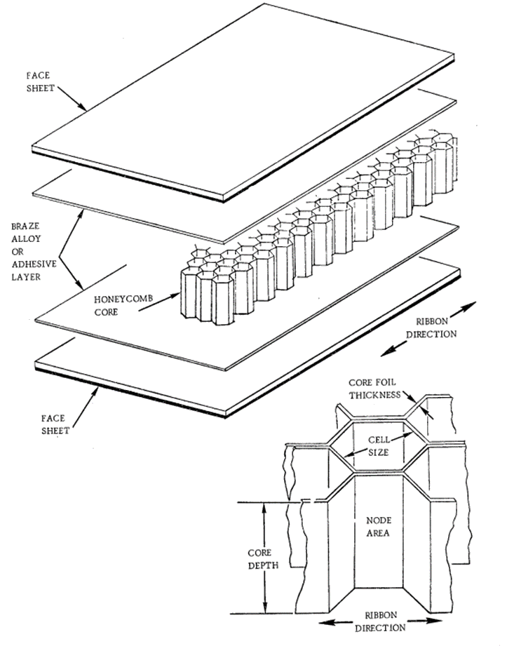
Figure 4.1.3‑6: Honeycomb Sandwich Construction (NASA CR-1457, 1969)
The effect of core on the out of place stiffness of a laminate panel is shown below, taken from (FAA-H-8083-31, 2012)
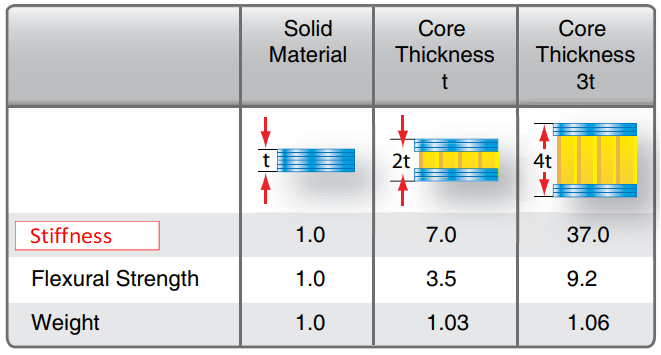
4.1.3‑7: The effect of Core on Strength and Stiffness (FAA-H-8083-31, 2012)Correction to Original Material in Red
Core Materials, from (FAA-H-8083-31, 2012)
Honeycomb: Each honeycomb material provides certain properties and has specific benefits. The most common core material used for aircraft honeycomb structures is aramid paper (Nomex® or Korex®). Fiberglass is used for higher strength applications.
- Kraft paper—relatively low strength, good insulating properties, is available in large quantities, and has a low cost.
- Thermoplastics—good insulating properties, good energy absorption and/or redirection, smooth cell walls, moisture and chemical resistance, are environmentally compatible, aesthetically pleasing, and have a relatively low cost.
- Aluminum—best strength-to-weight ratio and energy absorption, has good heat transfer properties, electromagnetic shielding properties, has smooth, thin cell walls, is machinable, and has a relatively low cost.
- Steel—good heat transfer properties, electromagnetic shielding properties, and heat resistant.
- Specialty metals (titanium)—relatively high strength-to-weight ratio, good heat transfer properties, chemical resistance, and heat resistant to very high temperatures.
- Aramid paper—flame resistant, fire retardant, good insulating properties, low dielectric properties, and good formability.
- Fiberglass—tailorable shear properties by layup, low dielectric properties, good insulating properties, and good formability.
- Carbon—good dimensional stability and retention, high-temperature property retention, high stiffness, very low coefficient of thermal expansion, tailorable thermal conductivity, relatively high shear modulus, and very expensive.
- Ceramics—heat resistant to very high temperatures, good insulating properties, is available in very small cell sizes, and very expensive.
Honeycomb core cells for aerospace applications are usually hexagonal. The cells are made by bonding stacked sheets at special locations. The stacked sheets are expanded to form hexagons. The direction parallel to the sheets is called ribbon direction.
Honeycomb core is available with different cell sizes. Small sizes provide better support for sandwich face sheets. Honeycomb is also available in different densities. Higher density core is stronger and stiffer than lower density core.
Foam: Foam cores are used on homebuilts and lighter aircraft to give strength and shape to wing tips, flight controls, fuselage sections, wings, and wing ribs. Foam cores are not commonly used on commercial type aircraft. Foams are typically heavier than honeycomb and not as strong. A variety of foams can be used as core material including:
- Polystyrene (better known as styrofoam)—aircraft grade styrofoam with a tightly closed cell structure and no voids between cells; high compressive strength and good resistance to water penetration; can be cut with a hot wire to make airfoil shapes.
- Phenolic—very good fire-resistant properties and can have very low density, but relatively low mechanical properties.
- Polyurethane—used for producing the fuselage, wing tips, and other curved parts of small aircraft; relatively inexpensive, fuel resistant, and compatible with most adhesives; do not use a hot wire to cut polyurethane foam; easily contoured with a large knife and sanding equipment.
- Polypropylene—used to make airfoil shapes; can be cut with a hot wire; compatible with most adhesives and epoxy resins; not for use with polyester resins, dissolves in fuels and solvents.
- Polyvinyl chloride (PVC) (Divinycell, Klegecell, and Airex)—a closed cell medium- to high-density foam with high compression strength, durability, and excellent fire resistance; can be vacuum formed to compound shapes and be bent using heat; compatible with polyester, vinyl ester, and epoxy resins.
- Polymethacrylimide (Rohacell)—a closed-cell foam used for lightweight sandwich construction; excellent mechanical properties, high dimensional stability under heat, good solvent resistance, and outstanding creep compression resistance; more expensive than the other types of foams, but has greater mechanical properties.
Sandwich structures are poor in damage tolerance: The step change in stiffness at the interface between the core material and the facing laminates creates an environment where damage growth is promoted. It is common for sandwich panels which have suffered damage and subsequently subjected to cyclic loads that the facing plies over the entire cored panel area can detach from the core material.
Sandwich materials are also prone to absorb moisture if the panel is improperly sealed or suffers damage to the facing plies. The repeated cycles of freezing and thawing of water absorbed into the core can detach the facing plies from the core. The failure of the rudder on Air Transat Flight 961 in 2005 was caused by this effect.
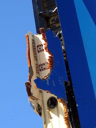
Figure 4.1.3‑8: Sandwich Composite Rudder Failure due to Water Ingress (Source: Aero News Network)
The analysis of composite laminate sandwich structures must consider different failure modes compared to solid laminates.
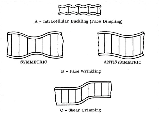
Localized Instability Modes
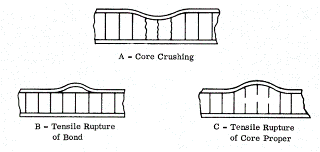
Ultimate Failures Precipitated by Face Wrinkling
Figure 4.1.3‑9: Sandwich Composite Panels, Possible Failure Mode (NASA CR-1457, 1969)
Note that the tension strength of a sandwich laminate is the total strength of the structural facing plies, the inclusion of a sandwich core affects the out-of-plane bending and buckling strength. The in-plane compression and shear strength of a sandwich laminate are less than for an equivalent solid laminate (taking the facing plies alone and laminating them together) because of additional failure modes that the inclusion of more material introduces such as those shown in Figure 4.1.3‑9.
For an in-depth discussion of sandwich composite specific analysis methods and failure modes see section 16.2.2.
To search the Abbott Aerospace Technical Library for ‘Composite Materials’ Clink the link below:
| Library Subject Search: Tag = Composite |