The method discussed in this section is defined in Chapter 2.3.1.7 of (![]() AFFDL-TR-69-42, 1986). In this reference the situation is described as “Bending Failure of Eccentrically Loaded Long Columns”.
AFFDL-TR-69-42, 1986). In this reference the situation is described as “Bending Failure of Eccentrically Loaded Long Columns”.
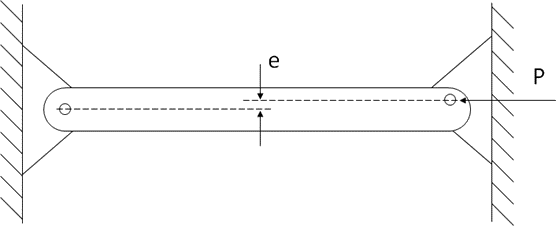
The bending effect can be generated from an eccentricity of the applied load – i.e. the load is applied some distance off axis from the axis of the column:
Or the bending effect can be created by a deviation, or eccentricity, of the load path within the column member.
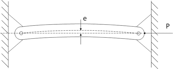
In both cases the solution is the same.
In the case where an initial moment is applied combined with a compressive end load, the deflection caused by the bending moment can be calculated and the resulting deflection can be used as the initial eccentricity.
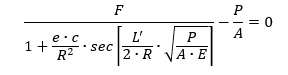
The solution to a beam column is achieved using the secant formula:
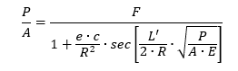
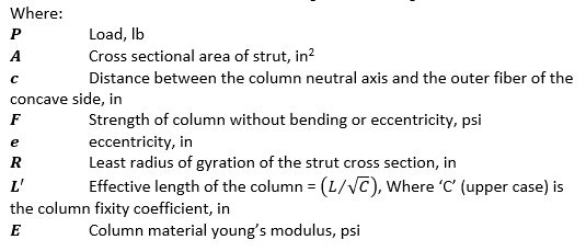
The solution to this equation is solved by either trial and error or iteratively for a value of P/A, which represents the reduced allowable for the beam-column, that satisfies the rearranged expression:
Note that this methodology does not account for the increased propensity for local buckling failures due to the combination of compressive end load and bending effects.
All physical columns will have some accidental initial curvature due to imperfections. In these cases, an equivalent eccentricity may be used to approximate the effects of the imperfections. It is recommended that L/400 is used as a conservative estimate for the equivalent eccentricity due to imperfections.
The spreadsheet for this method includes the tangent modulus column allowable combined with a beam column solution that is solved iteratively automatically.