12.2.6.1. Authors Note:
This chapter uses two main sources (![]() ECSS-E-HB-32-22A, 2011) and (
ECSS-E-HB-32-22A, 2011) and (![]() ESA-PSS-03-1202, 1987).
ESA-PSS-03-1202, 1987).
The 2011 document is a rewrite of the original 1987 document and the general descriptions are an improvement but the numerical analysis includes many errors that are not in the 1987 original.
However, much of the graphical strength data in the 1987 original reference is incorrect. Issue 1 of the 1987 report includes a note at the start of this report to this effect. This incorrect graphical data is omitted from the 2011 rewritten report.
Because of the condition of the two main references used for this report much of the descriptive material and illustrations are taken from (![]() ECSS-E-HB-32-22A, 2011), the analytical methods are taken from (
ECSS-E-HB-32-22A, 2011), the analytical methods are taken from (![]() ESA-PSS-03-1202, 1987).
ESA-PSS-03-1202, 1987).
Another, older reference (![]() US Forest Service Report No . 1845, 1955) has a method derived for out plane loading with some correlation between analysis and test which produces a similar load distribution with respect to radial distance as the method shown in section 12.2.6.6.
US Forest Service Report No . 1845, 1955) has a method derived for out plane loading with some correlation between analysis and test which produces a similar load distribution with respect to radial distance as the method shown in section 12.2.6.6.
12.2.6.2. Explanation:
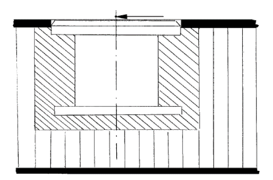
The most common means of mechanical attachment in sandwich panels is potted inserts. The potting procedure involves drilling through one or both face sheets, excavating the local core material, inserting the ‘insert’ and then injecting potting compound that sets it in place. Thus locking the insert to the cored panel in all six degrees of freedom.

 ECSS-E-HB-32-22A, 2011)
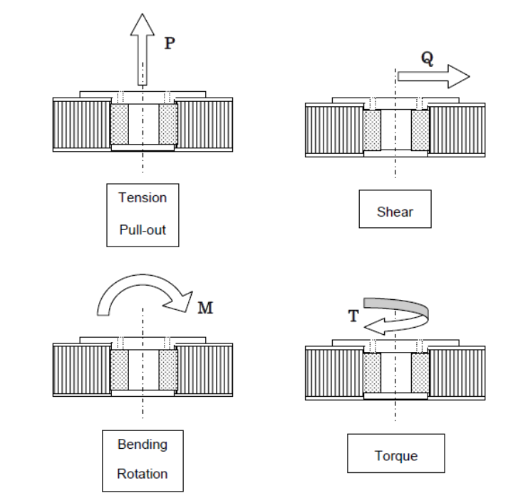
 There are 4 basic loading modes that a potted insert can react:
 ECSS-E-HB-32-22A, 2011)
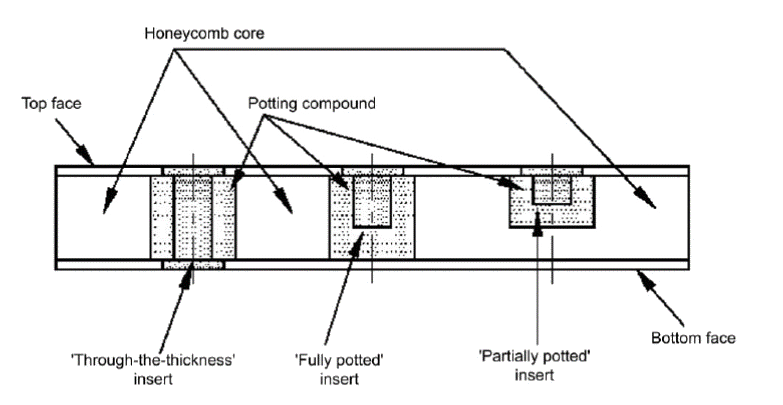
 There are 3 different types of potted insert installation configurations:
 ECSS-E-HB-32-22A, 2011)
 Inserts can be installed in any type of sandwich panel, with composite or isotropic face sheets. This section concentrates on potted inserts in sandwich structures with composite face sheets.
12.2.6.3. Nomenclature:
 ECSS-E-HB-32-22A, 2011)
 12.2.6.4. General Design Guidelines
- Compressive loads are transmitted via the face sheet in the area of the potting. The bracket or foot of the attaching member needs to exceed at least the maximum extension of the potting.
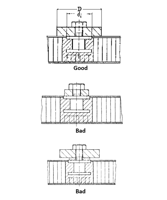
- The insert flange remains parallel to the face sheet such that under in‐plane loads it cannot move below the face sheet.
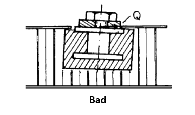
- Loads in the plane of the face sheet are usually transmitted by bearing pressure between the outer insert flange and the face sheet.
- The border of the face sheet around the insert is well supported to accommodate a high bearing stress, created inside by the potting and outside by the bracket or foot:
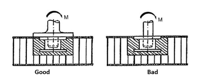
- Under a sufficient pre‐load of the insert bolt, minor or secondary bending moments are correctly reacted.
12.2.6.5. Guidelines Specific to Composite Face Sheets
For a sandwich panel with thin CFRP (Carbon Fiber Reinforced Plastic – a common term for carbon fiber laminates) face sheets, machining can be seen as problematical, although a thorough finishing of the protruding parts of the inserts is considered necessary in order to avoid damaging the surface ply. The machining process needs to be carefully investigated and reflected in the definition of the manufacturing procedure.
For thin face sheets made of CFRP with a flush mounted insert, another problem needs to be avoided under loads in‐plane in the face sheet. If the outer insert flange has even a small chamfer, possibly non‐intentional, the load transfer is reduced by bearing stress. The insert tends to undercut the face sheet.
 ECSS-E-HB-32-22A, 2011)
 This analysis method has been developed for honeycomb core but is also applicable for foam core.
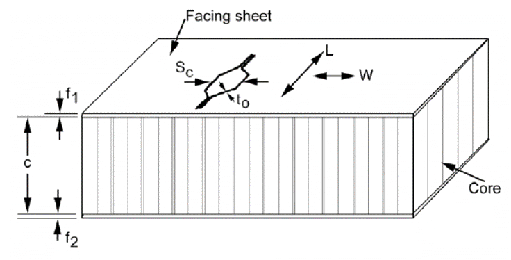
Much of the analysis methods that follow rely on the determination of the potting radius – the diagram below shows how this can prove difficult:
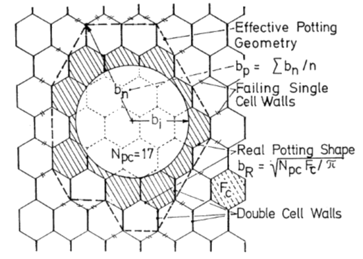
ESA-PSS-03-1202, 1987)
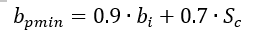
The effective minimum potting radius is given by the two following expressions for perforated and non-perforated core.
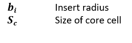
Where:
For perforated core:
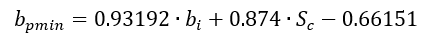
For non-perforated core:
For inserts in foam core panels the process used to install the insert should be reviewed, the amount of core excavation assessed and a conservative estimate of the likely effective potting radius should be made.
The minimum ‘real’ potting radius is a more conservative estimate of the potting radius and is determined using this expression:
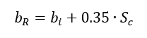
This expression is valid for perforated and non-perforated cores.
A spreadsheet to calculate these key parameters is available below:
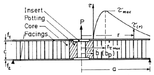
12.2.6.6. Tension/Compression Loading
This method gives the maximum axial tension or compression load that a potted insert can carry. This method is based on determining the maximum core shear stress just outside of the potting compound radius. The assumption inherent in the method is that the core strength is significantly less than the shear strength of the potting compound and therefore the potential shear-out failure modes in the potting compound are ignored (the shear stress is assumed to be zero until the core is responsible for through-the-thickness shear transfer).
This method is suitable for a fully potted insert:
 ESA-PSS-03-1202, 1987)
 Analysis Terms:
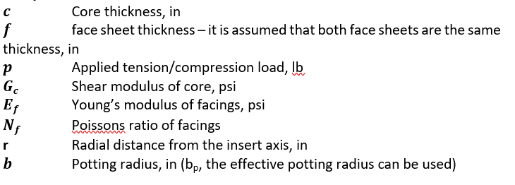
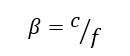
First, the ratio of core thickness to face sheet thickness must be determined. For this method to be accurate β > 10 is recommended.
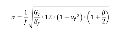
α is the ratio of out-of-plane stiffness between the core and the face sheets:
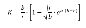
K is a factor that determines the distribution of shear stress in the core with distance from the insert axis:
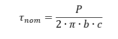
The shear stress in the core at any distance (r) from the insert axis is given by the following expression:
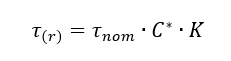
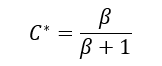
With the terms calculated as follows:
It is recommended that the shear stress is plotted for a range of (r) values and the resulting set of values surveyed to determine the maximum stress in the core (τmax).
The critical shear stress can be compared with the shear strength of the core, it is recommended that a 1.15 fitting factor is used for all potted inserts for general robustness and regulatory compliance:
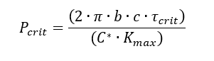
Ref (![]() ESA-PSS-03-1202, 1987) gives a method for converting the critical core shear stress into an allowable out-of-plane load:
ESA-PSS-03-1202, 1987) gives a method for converting the critical core shear stress into an allowable out-of-plane load:
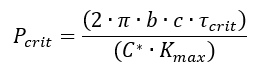
In which case the margin of safety is calculated as follows:
(![]() ESA-PSS-03-1202, 1987) has an approximate mathematical solution to determine the critical stress and critical radial distance from the hole. In the author’s experience, this method is not accurate and it is better to graphically determine the critical stress.
ESA-PSS-03-1202, 1987) has an approximate mathematical solution to determine the critical stress and critical radial distance from the hole. In the author’s experience, this method is not accurate and it is better to graphically determine the critical stress.
This spreadsheet uses this approach:
12.2.6.7. Inserts Loaded with In-Plane Shear Load
This method is for a partially potted insert. It can be used for a fully potted insert as it is conservative to do so.
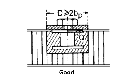
It is required that the diameter D of the foot of the attached part is at least as great as the typical potting diameter.
 ESA-PSS-03-1202, 1987)
 The shear load to which the insert can be submitted is given by the semi-empirical formula:
Where:
A spreadsheet method is available at the link below:
12.2.6.8. Inserts Loaded with a Moment
Similar to the shear load determination, this method is for a partially potted insert. It can be used for a fully potted insert as it is conservative to do so.
It is required that the diameter D of the foot of the attached part is at least as great as the typical potting diameter.
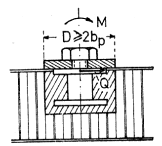 ESA-PSS-03-1202, 1987)
 The allowable moment on the insert – given the installation in Figure 12.2.6‑9 – is defined by:
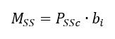
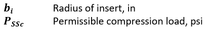
Where:
Ref (![]() ESA-PSS-03-1202, 1987) states that the value for PSS should be derived using the graphical solutions in the reference. However, the reference states that the graphical solutions are partly in error and should not be used. The tension/compression strength developed in 12.2.6.6 can be used. This approach is conservative.
ESA-PSS-03-1202, 1987) states that the value for PSS should be derived using the graphical solutions in the reference. However, the reference states that the graphical solutions are partly in error and should not be used. The tension/compression strength developed in 12.2.6.6 can be used. This approach is conservative.
Note that as this analysis is simple no individual spreadsheet has been developed for it.
12.2.6.9. Inserts Loaded with Torsion
In general, torsion loads on a single insert should be avoided by the use of coupled inserts or groups of inserts. As with shear and moment, the foot of the attachment should be no less than the potting diameter of the insert.
For metallic honeycomb core sandwich panels, the torsional load to which the single insert in a metallic core can be submitted is given by the formula:
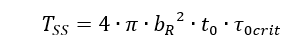
Where:
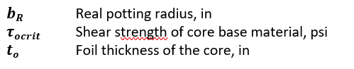
For non-metallic honeycomb core, the torsion strength should be determined by test.
A spreadsheet for this method is available at the link below:
12.2.6.10. Inserts Under Combined Loads
For inserts subject to combined out-of-plane and in-plane loads:
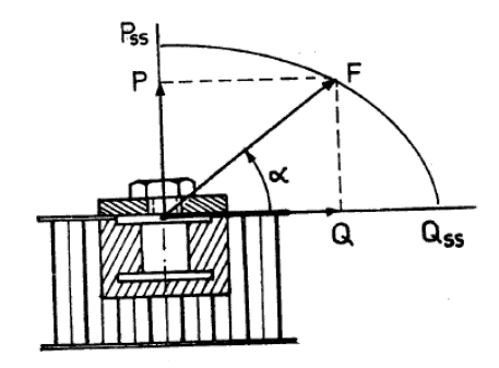 ESA-PSS-03-1202, 1987)
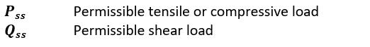
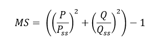
 The interaction of these two load effects is given by the following interaction:
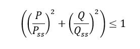
Where:
Therefore, the margin of safety is given by the following expression:
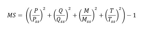
For Inserts subjected to combined out-of-plane load, shear load, moment and torsion:
The interaction of all of the possible load effects is given by the following expression.
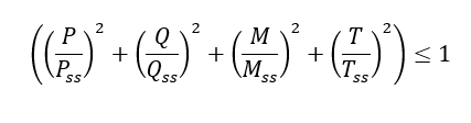
Therefore, the margin of safety is given by the following expression: