If all structure were only loaded in one manner, or mode, failure would be relatively simple to accurately predict. In practice, a single applied point load can result in complex stress states in complex structure, and complex loading can result in complex stress states in simple structure.
There are many ways to interact stresses. In this text, the most commonly used are covered.
Note that the analyst rarely analyses three-dimensional stress states by hand. Most aircraft structures can be adequately analyzed if the structure is planar and the magnitude of stress or load in the third dimension is not significant.
Where the structure and internal loads are such that the stress state is significantly three dimensional, it is preferable to use finite element analysis to predict stresses.
Three-dimensional calculations for stress tensors are presented for information and interest only.
It is worth noting that these criteria are directly applicable to isotropic materials only.
3.4.2.1. Principle Stresses
The solution may be attained using equations or the graphical construction of Mohr’s circle.
When an element of the structure is subjected to combined stresses such as tension, compression and shear, it is often necessary to determine resultant maximum stress values and their respective principal axes.
Relative Orientation and Equations of Combined Stresses. Where:
- fx and fy are applied normal stresses
- fs is applied shear stress
- fmax and fmin are the resulting principal normal stresses
- fsmax is the resulting principal shear stress
- θ is the angle of the principal axes
Sign Convention:
- Tensile Stress is positive
- Compression Stress is negative
- Shear Stress is positive as shown
- Positive θ is counter clockwise as shown
Principal Stresses in Two Dimensions
The relationship between general and principal stresses on a plane element is shown in the following figure:

Figure 3.4.2‑1: Geometric Relationship of Applied Stresses to Principal Stresses
Maximum principal stress:

Minimum Principal Stress:

The Angle of the principal stress field:

Maximum Shear Stress:

The relationship between the applied and principal stresses can be visualized using Mohr’s circle. See Section 3.4.3.1.
Note. The principal strains are related to the principal stresses by the following expressions:

Principal Stresses in Three Dimensions
The principal stresses in 3 dimensions can be calculated using the following expression. It should be noted that these are rarely used in hand calculations and are given here for reference only

Where:

There is a spreadsheet you can download for this method at this link:
3.4.2.2. Von-Mises Stresses
The Von-Mises stress is a resultant stress criterion that was initially developed to predict the point of yielding. In this case, the Von Mises stress is calculated and compared to the material yield stress allowable Fty.
It is also acceptable to use the Von Mises stress to predict failure by comparison with the material ultimate stress allowable Ftu .
It should be noted that because Von Mises stress is a resultant stress it is always positive regardless of the nature of the stress under examination, tension or compression.
Therefore, care must be taken when the Von Mises stress is used that compression stress effects (buckling, crippling) are not ignored because the stress appears positive (or tension).
Von Mises Stress in Two Dimensions
For general stresses:

Where the principal stresses are known

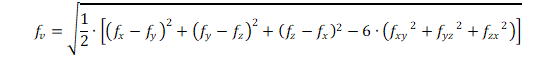
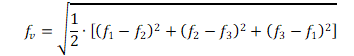
Von Mises Stress in Three Dimensions
For general stresses:
Where the principal stresses are known:
The two-dimensional Von Mises Stresses are generated for common cross-sections in the following spreadsheets: