Panel compression buckling is common when considering the primary failure mode of the upper wing skin panels, horizontal tail skins and vertical tail skins. Compression also contributes to the failure of other parts of the structure in combined failure modes.
 NACA-TN-3781, 1957)
 15.2.4.1. Compression Buckling Allowable Stress
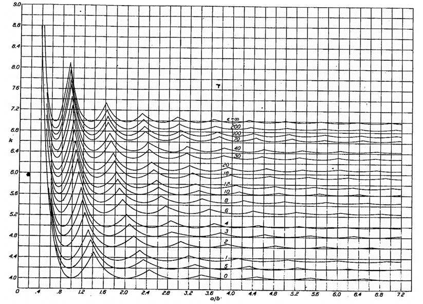
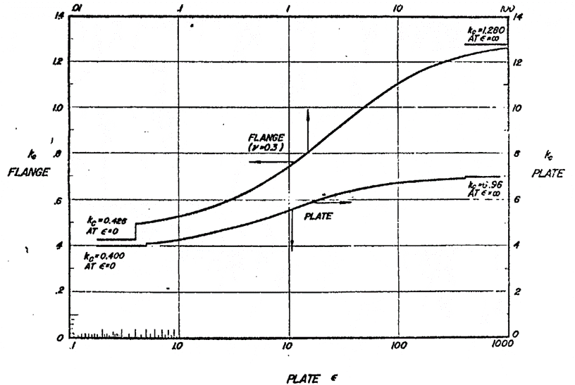
The compression buckling coefficient, kc, can be found once the panel aspect ratio is known from the following figure taken from (![]() NACA-Report-733)
NACA-Report-733)
 NACA-Report-733)
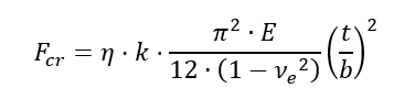
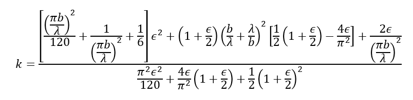
The compression buckling coefficient in the figure above is derived using the following expression:
This is covered in greater depth in section 15.2.4.3.
15.2.4.2. Panel with Simply Supported Edges
The simplest approach to panel compression buckling and the approach that is commonly used for initial sizing is to assume that and the panel is simply supported:
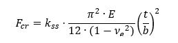
The coefficient for the simply supported edge condition is given by the following expression:
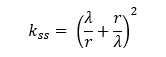

The minimum values of this curve for successive values of λ is shown below:
The minimum values of this curve for successive values of λ is shown below:
The simple and the general Panel compression buckling coefficients are calculated in this spreadsheet:Table
The simple approach to panel compression buckling is given in this spreadsheet:
Using this simple approach, to account for panel material plasticity if exceeds Fcy then limit Fcr to Fcy.
15.2.4.3. Compression Buckling Allowable Stress with Varying Panel Rotational Edge Fixity
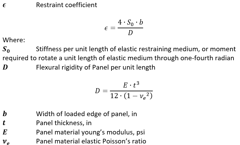
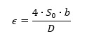
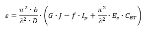
A simplified method allows for a quantified measure of the panel rotational edge stiffness, ε , this is defined by the following expression:
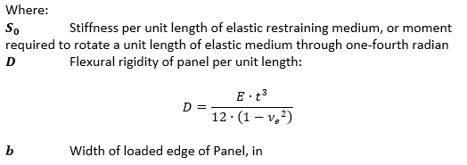
The value of ε can be calculated by taking the following approach. This approach is taken in part from (![]() NACA-TN-888, 1943).
NACA-TN-888, 1943).
The term ε can be calculated from this expression:
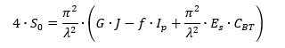
When this is combined with the initial expression for ε the expression for evaluating ε becomes:
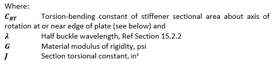
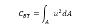
Of all these terms the CBT is a relatively little used cross section property and (![]() NACA-TN-888, 1943) is one of the few references that gives a method to determine this value.
NACA-TN-888, 1943) is one of the few references that gives a method to determine this value.
CBT is defined using the following expression:
and is described as “where u is the unit warping of the element of area dA from a reference plane through the shear center and normal to the axis when the angle of twist per unit length (dθ /dx) is unity”.
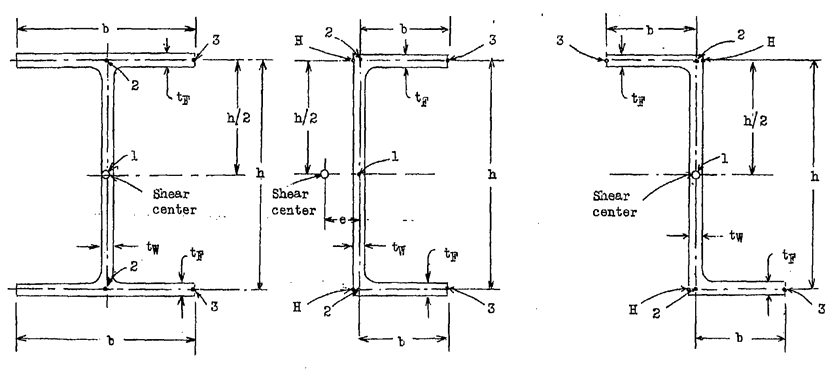
Thankfully the reference gives a set of expressions for for common cross sections:
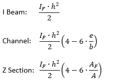
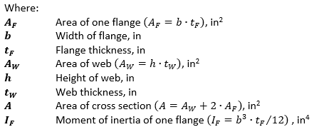
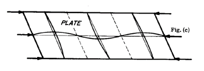
Further explained in the figure below:
The spreadsheet for this method is at the link below:
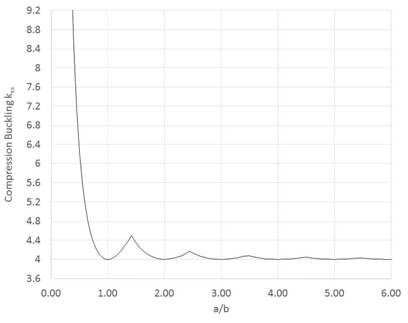
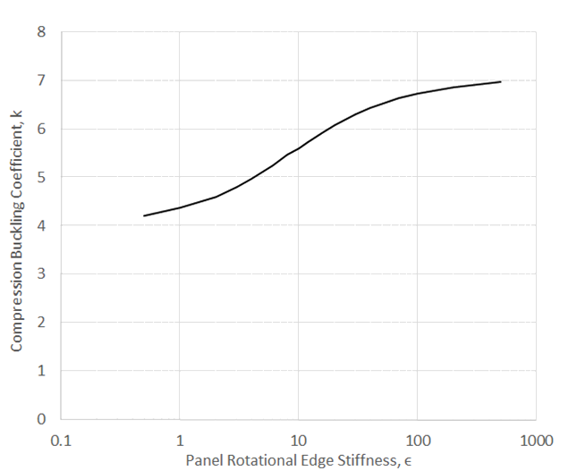
A view of how the simply supported compression buckling coefficient, k, changes with the value of is given in Figure 17 of (![]() NACA-TN-3781, 1957):
NACA-TN-3781, 1957):
 NACA-TN-3781, 1957)
 The lower line on the graph above defines the relationship between k and for a panel in compression buckling.
The spreadsheet method for estimating the effect on k for edge rotational edge fixity is given at the link below:
Note that this method of accounting for panel edge fixity correlates well to the value of k calculated using the general expression which is shown in Figure 15.2.4.
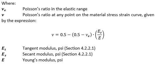
15.2.4.4. Compression Buckling Allowable Stress with Full Elasto-Plastic Material Data
If the calculated compression buckling stress is approaching the compression yield stress (Fcy) of the material the elastic compression buckling allowable could be optimistic. If a more nuanced approach than limiting the buckling stress to Fcy is required, the compression buckling allowable should be modified using the plasticity correction factor η.
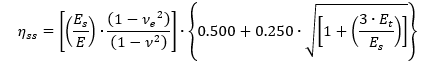
From (![]() NACA-TN-3781, 1957) for compression buckling the plasticity correction factor for a long simply supported panel is:
NACA-TN-3781, 1957) for compression buckling the plasticity correction factor for a long simply supported panel is:
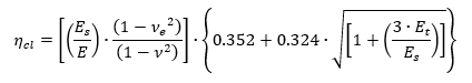
the plasticity correction factor for a long, clamped panel is:
Plotting these two plasticity correction factors for a typical aluminum give the following result:
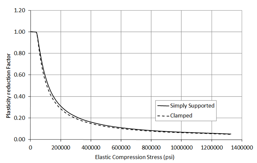
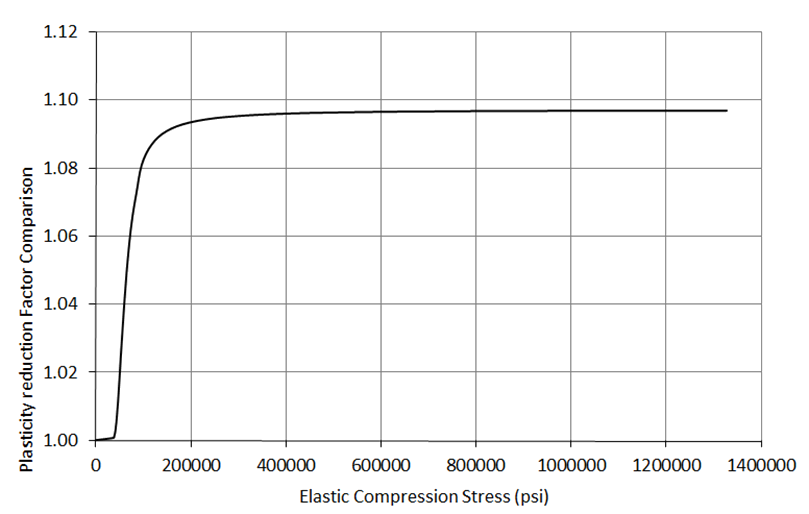
There is only a small difference between the two factors (less than 10%). It is recommended that the plasticity correction factor for clamped panels is used for all panels as it provides a simpler, conservative solution.
Like the shear buckling allowable corrected for material plasticity, the plasticity correction factor for compression buckling can be used to produce a curve that relates the elastic buckling stress with the plastic buckling stress.
Once the graph has been plotted the elastic shear buckling allowable can be plotted on the x-axis, project upwards to the curve and read across to the Y-axis to give the compression buckling allowable corrected for plasticity.
Superimposing the simpler approach of limiting Fcr to Fcy over the Elastic vs Plastic shear buckling stress curve gives the following result:
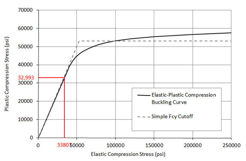
For the sample material (and for most ductile materials) the simple approach does give a reasonable approximation to the correctly calculated plastic buckling allowable. A spreadsheet is available for this method at the link below:
15.2.4.5. Effect of Central Hole on Panel Compression Buckling Allowable
In the process of writing this section many references were reviewed. The single best summary of results is contained in (![]() NASA-TM-1998-206542, 1998). This paper is a summary of the results of a Finite Element study looking at the effect of circular and square holes on isotropic Panel buckling. Other references that are in general agreement include (
NASA-TM-1998-206542, 1998). This paper is a summary of the results of a Finite Element study looking at the effect of circular and square holes on isotropic Panel buckling. Other references that are in general agreement include (![]() NASA-TP-3024, 1990).
NASA-TP-3024, 1990).
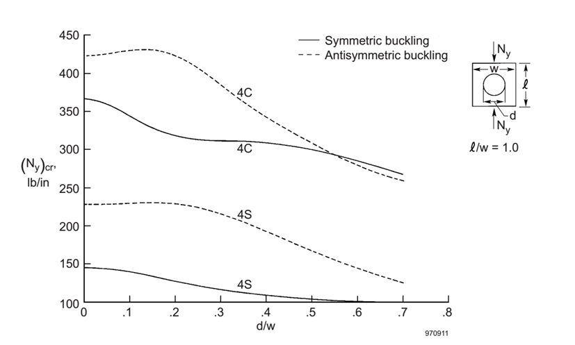
The figures in (![]() NASA-TM-1998-206542, 1998) are given in terms of changes in absolute buckling values. These results have been reinterpreted to give a reduction factor for compression buckling factor k.
NASA-TM-1998-206542, 1998) are given in terms of changes in absolute buckling values. These results have been reinterpreted to give a reduction factor for compression buckling factor k.
In the following figures the most onerous reduction from either the symmetric buckling or antisymmetric buckling modes have been used.
Note: The reduction factors are based on Figure 17 of (![]() NASA-TM-1998-206542, 1998). This is reported as having ‘free’ edges – edges which are free to move in-plane. However, the results for a hole diameter of 0 in agree with the results for a simply supported panel without a hole from table 4 of the same reference. This result also agrees with independent checking done for panels with edges restrained in translation and free in rotation during the compilation of this section. It is therefore assumed that the reference is in error and Figure 17 is representative of panels with a hole where the edges are restrained for in-plane translation.
NASA-TM-1998-206542, 1998). This is reported as having ‘free’ edges – edges which are free to move in-plane. However, the results for a hole diameter of 0 in agree with the results for a simply supported panel without a hole from table 4 of the same reference. This result also agrees with independent checking done for panels with edges restrained in translation and free in rotation during the compilation of this section. It is therefore assumed that the reference is in error and Figure 17 is representative of panels with a hole where the edges are restrained for in-plane translation.
 NASA-TM-1998-206542, 1998)
 It was found that the critical panel aspect ratio was 1:1 (square). As long as the panel is loaded in compression aligned with the long dimension, use of the square panel data is conservative.
This method is not applicable for panels loaded in compression across the short dimension.
As noted, the ratio of greatest reduction in buckling strength for each of the clamped and simply supported curves was calculated and plotted:
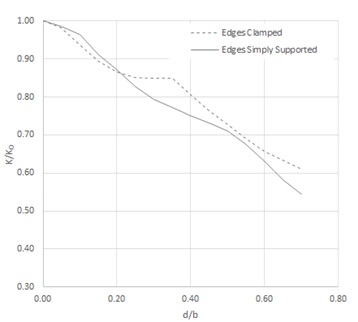
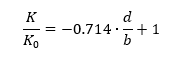
A simple conservative linear approximation can be used that is applicable to both simply supported and clamped panels.
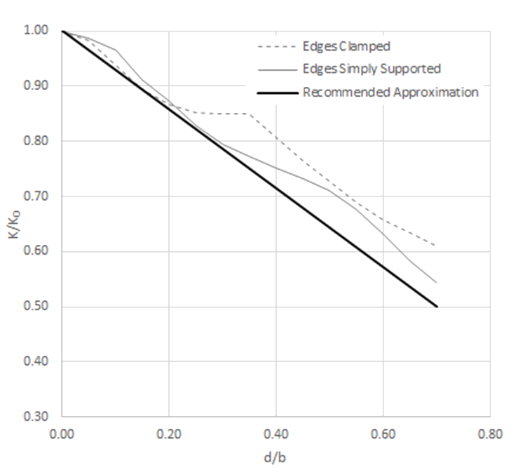
The equation for this linear approximation is:
A spreadsheet method is available at the link below: