NASA-BRIEF-64-10080
- Version
- 70 Downloads
- 112.74 KB File Size
- 1 File Count
- August 19, 2017 Create Date
- August 19, 2017 Last Updated
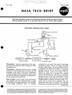
Improved Insertion-Loss Tester
The problem: Accurate measurement of the inser-
tion loss of rf components while avoiding the effects
of amplifier drift.
The solution: Balancing currents across a bridge
transformer with shorted probes and then with the
component to be tested in the circuit. Adjustments
are made to obtain a null on a sensitivity meter in each
case and the difference in adjustment is interpreted to
give the component’s insertion loss.
How it's done: The rf output of the input bolom-
eter is applied to the ratio transformer that is tapped
to the primary of a bridge transformer. The secondary
of the bridge transformer drives an amplifier
connected to a null meter. The output of the bridge
transformer primary is fed to an output bolometer
through a phase shifter. To test the insertion loss of
a component, the directional couplers are connected
(shorted) and the tap on the ratio transformer
adjusted to obtain a null on the meter. The tap
position for meter null is recorded. The couplers
are now disconnected and, with the test component
inserted, the tap on the ratio transformer is again
adjusted to obtain a null on the meter. Once an almost
complete balance is obtained, the phase shifter is ad-
justed until an actual null is obtained. This tap
position'for meter null is recorded.
| File | Action |
|---|---|
| NASA-BRIEF-64-10080 Improved Insertion-Loss Tester.pdf | Download |
Comment On This Post