17,005 Documents in our Technical Library
2464515 Total Downloads

Newest Additions

NASA-RP-1060 Subsonic Aircraft: Evolution and the Matching of Size to Performance
AA-CP-20212-001
AA-CP-20212-001
ADPO10769 Occurrence of Corrosion in Airframes
The purpose of this lecture is to provide an overview ...
MIL-STD-1759 Rivets and Rivet Type Fasteners Preferred for Design
The purpose of this book form standard is to provide ...
MIL-STD-810G Environmental Engineering Considerations and Laboratory Tests
This standard contains materiel acquisition program planning and engineering direction ...

ARC-RM-445

ARC-RM-445
  • Version
  • 158 Downloads
  • 1.07 MB File Size
  • 1 File Count
  • June 16, 2016 Create Date
  • June 16, 2016 Last Updated
Scroll for Details

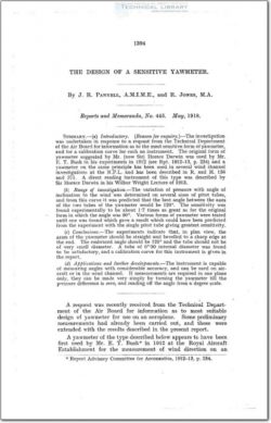
The Design of a Sensitive Yawmeter

ARC-RM-445 The Design of a Sensitive Yawmeter

As the instrument has been described elsewhere, it will suffice
here to state that the yawmeter consists essentially of two pitot
tubes set with their axes inclined to the wind direction so that
when that inclination is varied there is a difference of pressure
between the two tubes. Two forms of yawmeter are shown
diagramatically in Fig. 2. An instrument was constructed
at the National Physical Laboratory (and described in Report
R. and M. 156) with two pairs of tubes for measurement of direc-
tion in two perpendicular planes ; a suction tube, similar to the
one on Mr. Bush’s instrument, was added for measurement of
velocity. The present investigation was directed to determining
the most sensitive arrangement of tubes for measurement of
direction only in one plane.

Method of ewperimcnt.—~Since the sensitivity of the yawmeter
depends essentially on the rate of change of pressure with angle
in the tubes of which it is constructed, the first step was to deter-
mine this variation ior a pitot tube alone. This was done for
the pitot tube of the National Physical Laboratory standard
head, and as the apparatus was erected it was thought useful
to observe also the variation of pressure difierence between the
pitot and static pressure tubes of this head for various inclinations
to the wind. Inspection of the curve thus obtained suggested
that the maximum sensitivity would be obtained by placing
the two tubes of the yawmeter with their axes inclined at 120°
to each other (mutually at 60° to the wind direction) instead of at
90° as previously adopted. In order to test this assumption
a yawmeter was made in which the angle between the tubes was
90° and after calibration this angle was increased to 120° (No. 1,
Fig. 2). The sensitivity of the latter was found to be more than
1-7 times that of the former and this angle was adopted for
all subsequent instruments. This yawmeter was constructed of
tube 0’530 internal and 0”-375 external diameter, but it was
found that the sensitivity was less than that which was expected
from an examination of the curve for the pitot of the standard
head, on the assumption that the two tubes of the yawmeter
did not interfere with each other. The sensitivity was improved
somewhat by bevelling the tubes (as shown in Fig. 2), but the curve
still fell below that deduced. Accordingly a yawmeter was con-
structed of the nearest tube to that of the standard head which
was available, a single tube being shown at No. 3A in Fig. 1.
An experiment showed this instrument to be rather less sensitive
than the one constructed of the O”-30 tube.

FileAction
ARC-RM-445 The Design of a Sensitive Yawmeter.pdfDownload 

Comment On This Post

Your email address will not be published. Required fields are marked *

ARC-RM-445

ARC-RM-445
  • Version
  • 158 Downloads
  • 1.07 MB File Size
  • 1 File Count
  • June 16, 2016 Create Date
  • June 16, 2016 Last Updated
Scroll for Details

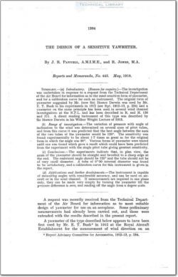
The Design of a Sensitive Yawmeter

ARC-RM-445 The Design of a Sensitive Yawmeter

As the instrument has been described elsewhere, it will suffice
here to state that the yawmeter consists essentially of two pitot
tubes set with their axes inclined to the wind direction so that
when that inclination is varied there is a difference of pressure
between the two tubes. Two forms of yawmeter are shown
diagramatically in Fig. 2. An instrument was constructed
at the National Physical Laboratory (and described in Report
R. and M. 156) with two pairs of tubes for measurement of direc-
tion in two perpendicular planes ; a suction tube, similar to the
one on Mr. Bush’s instrument, was added for measurement of
velocity. The present investigation was directed to determining
the most sensitive arrangement of tubes for measurement of
direction only in one plane.

Method of ewperimcnt.—~Since the sensitivity of the yawmeter
depends essentially on the rate of change of pressure with angle
in the tubes of which it is constructed, the first step was to deter-
mine this variation ior a pitot tube alone. This was done for
the pitot tube of the National Physical Laboratory standard
head, and as the apparatus was erected it was thought useful
to observe also the variation of pressure difierence between the
pitot and static pressure tubes of this head for various inclinations
to the wind. Inspection of the curve thus obtained suggested
that the maximum sensitivity would be obtained by placing
the two tubes of the yawmeter with their axes inclined at 120°
to each other (mutually at 60° to the wind direction) instead of at
90° as previously adopted. In order to test this assumption
a yawmeter was made in which the angle between the tubes was
90° and after calibration this angle was increased to 120° (No. 1,
Fig. 2). The sensitivity of the latter was found to be more than
1-7 times that of the former and this angle was adopted for
all subsequent instruments. This yawmeter was constructed of
tube 0’530 internal and 0”-375 external diameter, but it was
found that the sensitivity was less than that which was expected
from an examination of the curve for the pitot of the standard
head, on the assumption that the two tubes of the yawmeter
did not interfere with each other. The sensitivity was improved
somewhat by bevelling the tubes (as shown in Fig. 2), but the curve
still fell below that deduced. Accordingly a yawmeter was con-
structed of the nearest tube to that of the standard head which
was available, a single tube being shown at No. 3A in Fig. 1.
An experiment showed this instrument to be rather less sensitive
than the one constructed of the O”-30 tube.

FileAction
ARC-RM-445 The Design of a Sensitive Yawmeter.pdfDownload 
17,005 Documents in our Technical Library
2464515 Total Downloads

Search The Technical Library

Newest Additions

NASA-RP-1060 Subsonic Aircraft: Evolution and the Matching of Size to Performance
AA-CP-20212-001
AA-CP-20212-001
ADPO10769 Occurrence of Corrosion in Airframes
The purpose of this lecture is to provide an overview ...
MIL-STD-1759 Rivets and Rivet Type Fasteners Preferred for Design
The purpose of this book form standard is to provide ...
MIL-STD-810G Environmental Engineering Considerations and Laboratory Tests
This standard contains materiel acquisition program planning and engineering direction ...