Working from Home

Hardware

I have been working from a mixture of different rooms in my home, hotels, private offices and project offices for 12 years. When I am at home I can control the equipment I use and the environment I work in, when I am on the road I have less control.

So I need a single setup that uses the same basic computer and gives me a range of options for layout and setups that I can use effectively in my home and regular office and when I am travelling.

I also have several set ups that I use at home. I work a lot – around 16 hours a day. In order to spend some time in the presence of my family I do my evening work in a shared space. So I have two home setups. One for the home office (for office hours) and one I use on the dining table in the evenings and weekends. (I also have a ‘real’ office, but I don’t work out of there too often, what’s the point?)

The central processing unit: I use a PC laptop. I don’t care too much about the specification or manufacturer. I have had good and bad luck with HP, Dell, ASUS, ACER and just about everyone else. They always tend to start to get glitchy after two years so I have to ‘refresh’ my laptop on a regular basis.

Computers ‘n’ stuff

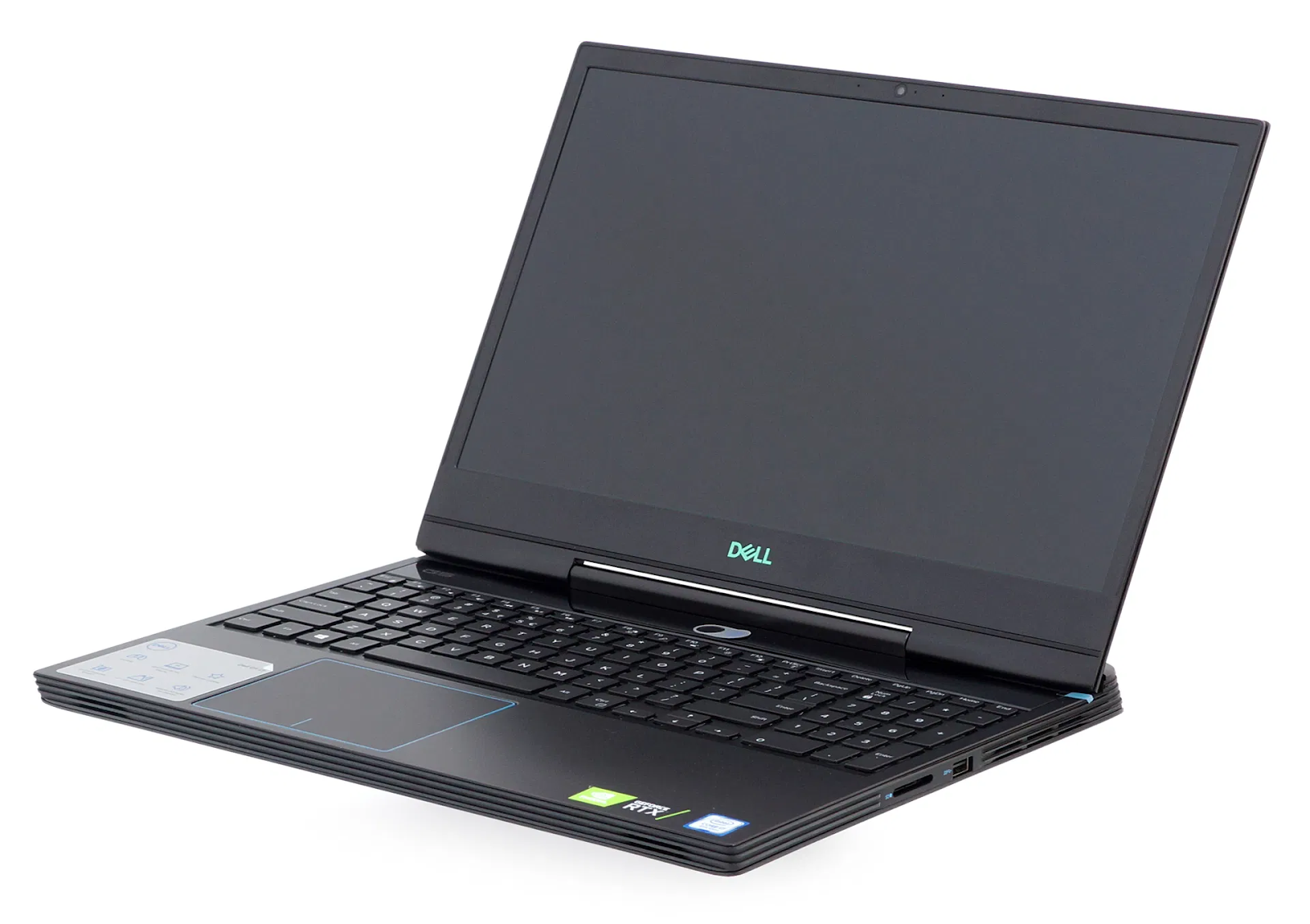
Right now I have a Dell GS5590. This has (so I am told) some processors that are ‘pretty fast’. I used to build my own PC’s and used to be into all of the nerdy specifications. In the last few years computers have just become a tool so I don’t care too much about the details and long as they do what I want. In general I need at least 16G ram and a large solid state hard drive. If your storage is fast enough the page file is a reasonable substitute for more RAM. I also need a good graphics card.

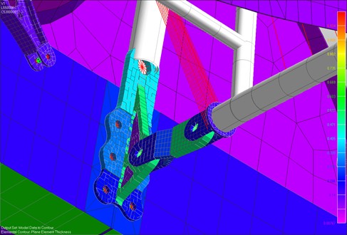
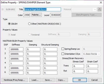
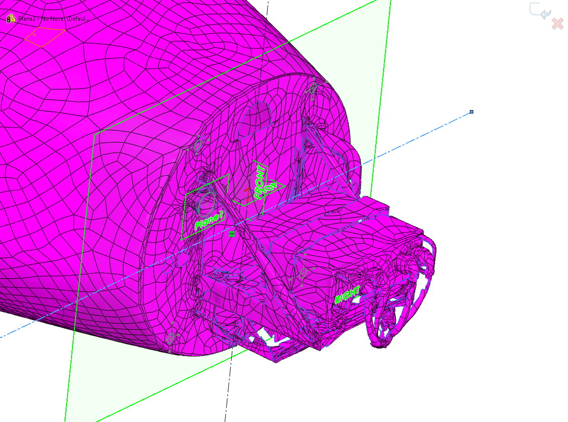
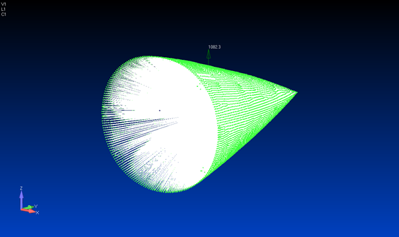
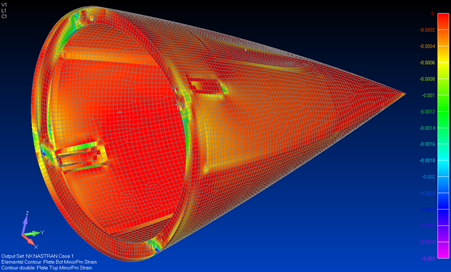
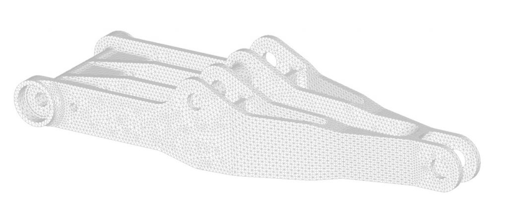
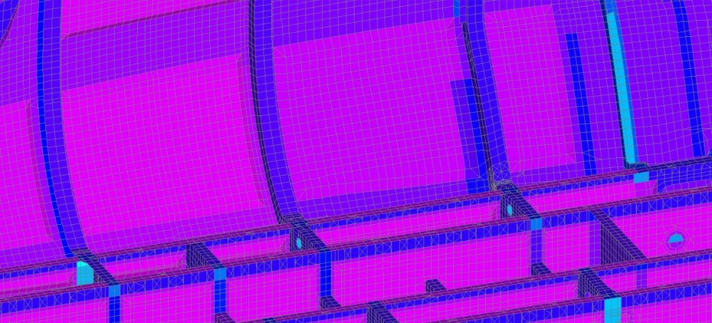
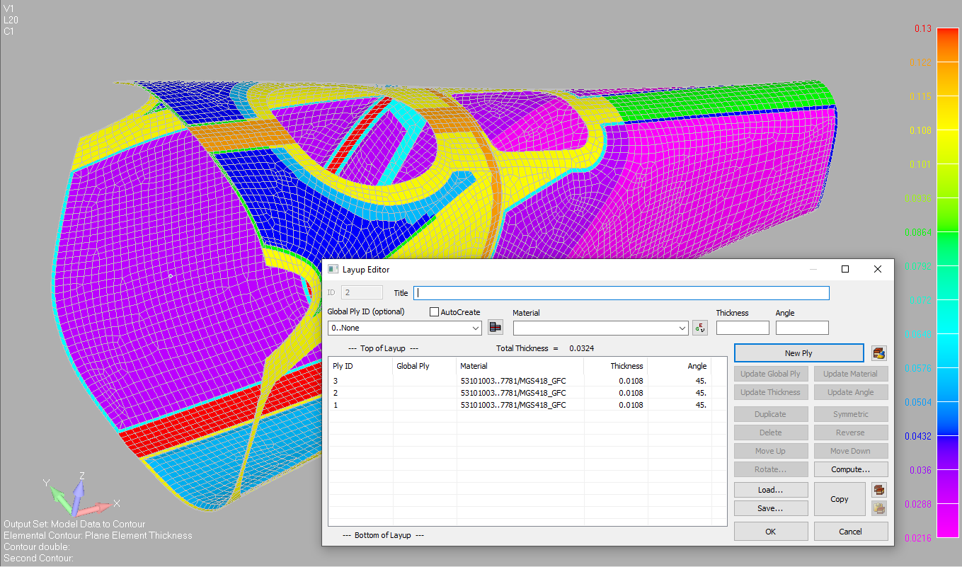
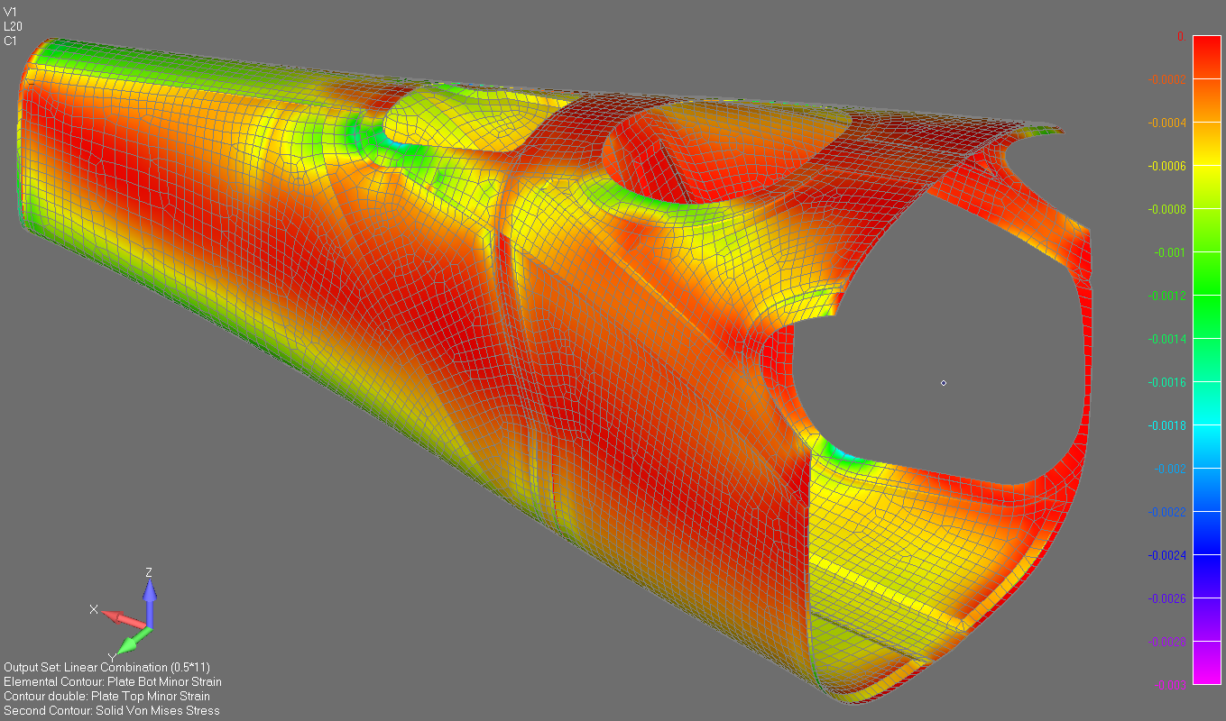
I run CAD and Finite element analysis and it gets a little slow very occasionally but I usually run up against the limits of the software before I hit the limits of the hardware.

The last laptop I had was a high end Alienware Laptop – that was very capable but very heavy and was a pain when I was travelling. This new Dell has proven to be a good compromise between performance and convenience. My son is now the owner of the Alienware behemoth. We are both happy.

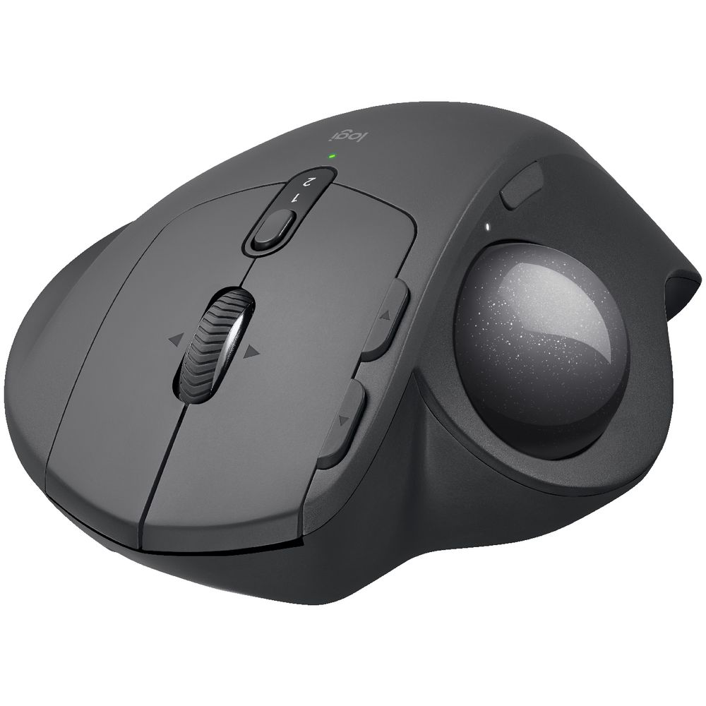
I use a trackball rather than a mouse, years of long hours of work means you start to value the condition of your carpal tunnels more than you thought you ever would…. – I have a logi MX Ergo trackball. I can recommend this without hesitation. It needs cleaning twice a week or so, but I regard mine as indispensable.

I use a range of screens depending on where I am, but the components are generally the same.

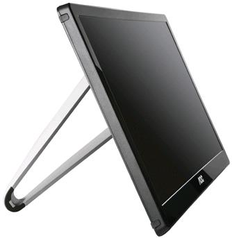
I always have a USB screen – this is great for travelling and at home. I have a AOC 15.6″ 1366×768 USB Monitor (E1659FWU). I had a ASUS USB screen before this one – this one is better and I can recommend it. I use this in both landscape and portrait orientation and it has a reasonable range of view angles in both modes.

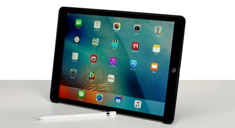
I use 12.9in ipad pro for music and podcasts. I will usually slave this to a bluetooth home cinema soundbar with a reasonable subwoofer. I have two soundbars that I switch between  depending on where I am in the house – a Samsung and a Polk Audio. I used to be a studio sound engineer (in a previous life) and the sound quality you can get for a couple of hundred bucks today is fabulous.

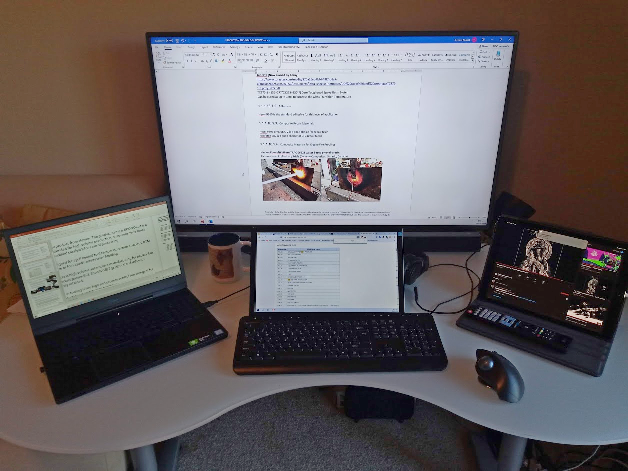
My third monitor is the variable. In my home office I now use a 65in HD TV for my third monitor. My current home office arrangement is shown below:

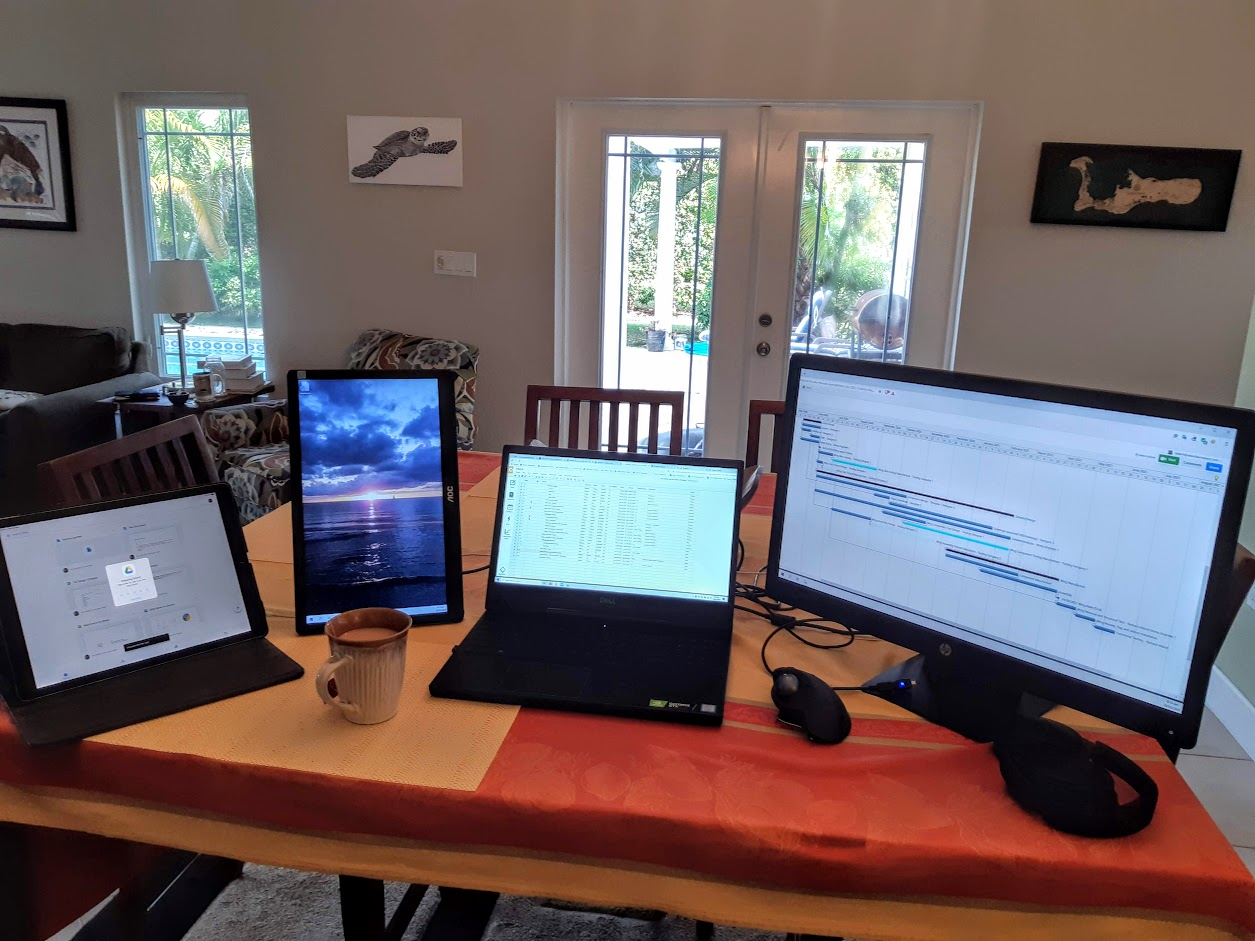
In the evening I lose the USB keyboard and use a standard desk monitor in the following arrangement (a cup of tea is optional):

When I am travelling I take the laptop, my AOC USB monitor and the Ipad with me. I use a small projector and the wall of the hotel room as a third monitor. I bought this 5 years ago on a whim and it has been incredibly useful travelling for working, making presentations and teaching class.

Wne I combine this with a little Bose bluetooth speaker I have my portable ‘hotel cinema’ for when I travel. This little projector has been dropped, beaten up and generally abused and has been solid and reliable. One of the best pieces of equipment I have ever bought. My next projector will be an aaxa product.

When I am working in the evening and travelling I use a set of Bose sound cancelling headphones. These are also fantastic for long flights at blocking out the drone of the aircraft engines and allow me to work and nap in peace.

Your Environment

You should arrange your environment to be the most comfortable and useful to you. You have the opportunity to make it the best for you. Keep on tweaking and changing it until it is the best you can make it. Get the desk, chair and keyboard height  right. Get hold of the best office chair you can find. It may not seem important at first but after a month you will find parts of you will start to hurt if you get this wrong.

Get as large a desk as possible. Desk real estate (like screen real estate) is always useful and you can never have enough.

Work in a room with a door. Being able to close a door on the outside world (barking family dogs, children and general household noises) when you have to concentrate or get on an important call is invaluable.

Work so you can look out of a window. If you spend 10+ hours a day staring at a screen it is very good for your eyes to look up on a regular basis and focus on something in the distance. It is also generally good for morale to be able to see beyond your immediate environment.

I listen to music when I work and occasionally listen to news or other spoken word content (audio books, podcasts, etc) but only when I don’t have to concentrate too hard. I favor post-rock, modem stoner rock and some jazz/electrical crossover music for work. I tend to avoid music I am familiar with (too engaging) and use my time working to listen to new music (and the occasional golden oldie).

Current work Playlist: Tycho, Kal-el, Yawning Man, Valley of the Sun, Tommy Guerro, We Lost the Sea, Earth, Villagers of Ioannina City, The Elder, Mount Hush, Hawkwind. 

Your Routine

Over years of working independently I find that the earlier I start the better I work and the more motivated I am. You also get a period of time guaranteed to be interruption free so you can focus on your work. I get up at 5am, get dressed, make coffee, grab breakfast and I am usually at my desk by 5:15am. I can usually get 2-3 hours of completely interruption free work first thing in the morning. No clients, subcontractors, employees or family members to engage and interrupt me.

Getting this amount of work done early on sets me up for the day. I break for lunch when I get hungry – usually around 11am and eat at my desk. I always base my timing around my clients. If there is a meeting or a call I will always regard my personal routine as very elastic. Clients come first and facetime always takes priority over everything else. When you are working remotely video calling and conferencing is vital. It is easy to get psychologically isolated from a project or group if you use email only, this can lead to a lack of commitment and involvement on your part and also from the client side. This can be the beginning of the end of a client relationship.

 have learned not to place a limit on the hours I work. Working from home or offsite from your own private office is a privilege. You should respond to your clients by doing whatever it takes to make them happy, making yourself available and working whatever hours is required to do the best job you can.

Technical References

For stress analysis work there are two indispensable books, and I keep paper copies of those to hand:

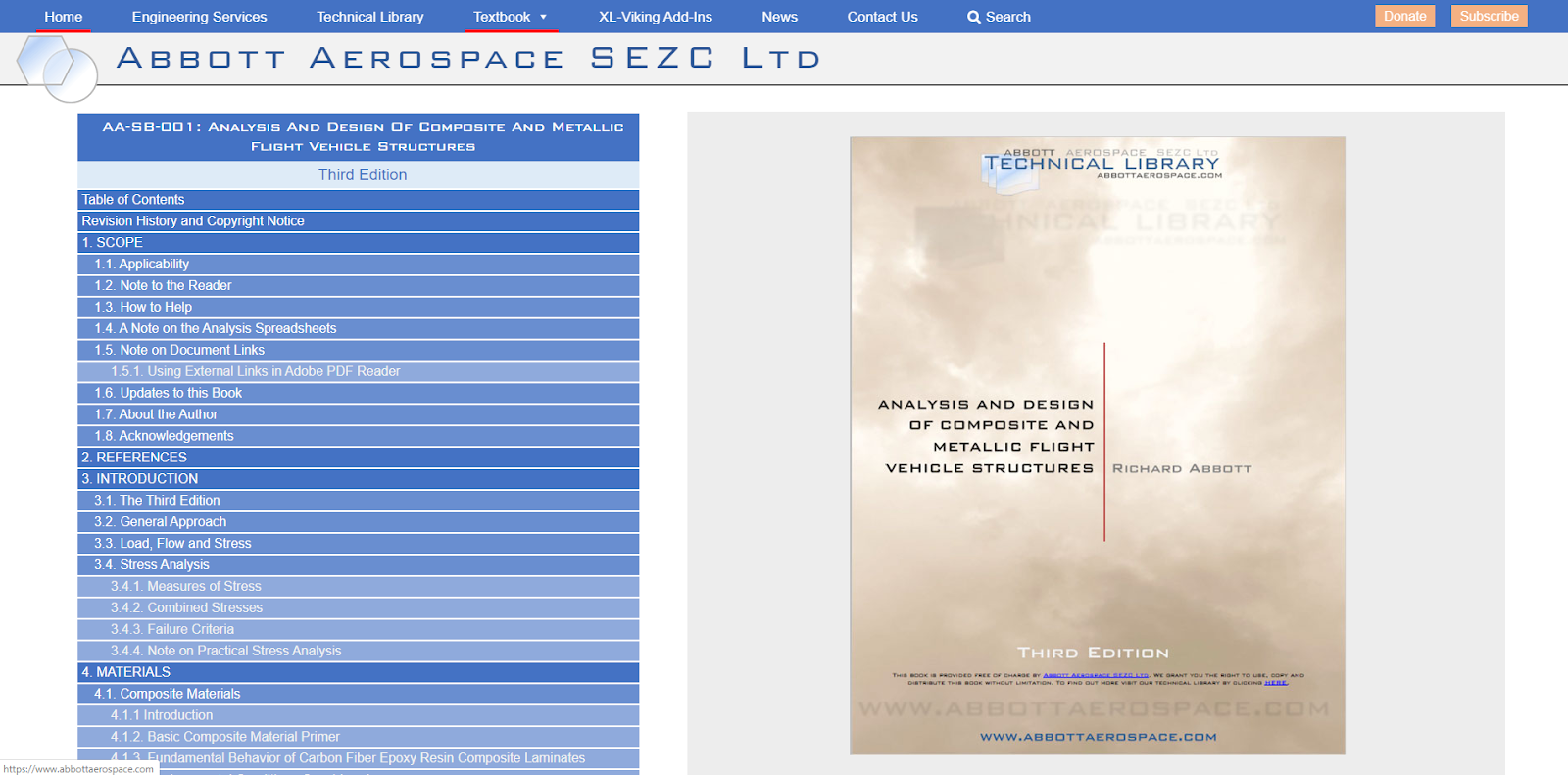
Bruhn and Roark – I also keep copies of Peery and Gudmundsson close by. For everything else there is the Abbott Aerospace Technical Library.

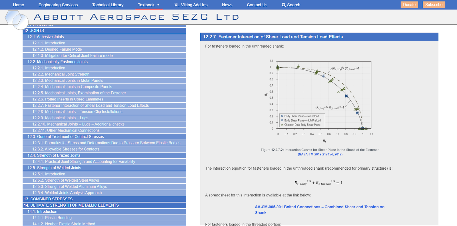
The technical library was created for this situation. We have people working from remote locations and I needed a way to provide a consistent set of standard references and methods in a way that could be searched and linked to – all items in the library have a fixed web address. We also had to allow the latest updates to be simultaneously available to everyone. The web format also keeps people from changing file names, saving over files or moving files around on a shared server.

Many companies have internal web based intranet systems for this purpose. As we mainly use public domain sources (and we choose to make all of our internally created methods and documents public domain) it was logical to use the internet rather than a secure internal system.

Security is difficult and expensive and if you decide not to use it and arrange yourself accordingly (not using proprietary or client data), life is much easier.

General Tips

  • When you are working from home it is as if you are at work. Dress and act accordingly.
  • Encourage your family/flatmates to treat you like you were at work. Avoid interruptions and distraction during office hours
  • Avoid putting your office in your bedroom. Keep your work in a seperate room from where you sleep.
  • Keep a log of your hours and activities (I use my google calendar to log hours for my various clients). 
  • If you are isolated physically communication is vital. Always make yourself available for professional/technical conversations. I use every available device and app so my clients, partners and subcontractors can contact me any time and we can have a face to face conversation: Google Hangouts, Skype, Zoom, What’sapp, Cell phone, Text.
  • As you will be video calling, make sure you, your background and whatever else is in the field of view of your camera is professional and appropriate.
  • If you need to take a 10 minute break to stretch your legs, take a break, go into a different room or step outside. In the bad old days a lot of us used to take cigarette breaks every couple of hours. Other than catching a nasty disease and shortening your lifespan there is value in stepping out for a few minutes every couple of hours to interrupt your flow of thought and have a quick mental reboot.

Composite Modeling and Analysis Part 4. – Joints

A version of this article first appeared in the February 2020 edition of our free newsletter, to subscribe click here

We return to composite (and other structure) finite element modelling and tackle joints in this issue. To state the obvious joints are where different pieces of structure are joined to each other.

For most joint modelling we are interested in extracting the loads from the model at the joint interface and carrying out an external calculation to give a margin of safety.

This is because the behaviour of joint is more complex than the general structure and a finite element model requires a high degree of complexity to represent all of the aspects and features of a joint (bonded or mechanically fastened). It is much more efficient to make the stiffness of the area of the joint broadly representative and design the mesh to make it easy to extract the local loads.

At least that’s the correct approach for larger scale models. For smaller scale models I have seen ( and created) detailed models of mechanical fasteners and adhesive bond lines. But whatever those more detailed models tell me I always end up relying on extracting the loads and running a hand check to make sure the joint will be good.

Adhesively bonded joints:

For adhesively bonded joints in large scale models we will model the flange that is bonded into the skin mesh. This is done to better model the stiffness of the vonded joint interface. This also helps with the local stiffness of this region for the buckling solution

We have found that if the core ends in the correct position and the bonded flange against the skin is not modelled you can start to get compression buckles of the stretch of uncored skin.  This is because the bonded flange creates additional out of plane bending stiffness that stops the compression buckle in these regions.

The element loads form the rib (or frame) web can ex extracted and used to check the bondline for shear transfer and peel in the following way.

This is the simplest and most robust way we have found to deal with adhesive bonds at a large scale.

For detailed models we will sometimes model the adhesive as solid elements, this is the finite element model for the edge of transparency:

One of these interfaces uses a bonded joint, in this case we modelled the joint as a set of solid elements that share the nodes of the laminate elements either side of the joint. This does not help us determine if the bond is likely to fail, but it is a more accurate representation of the stiffness of the intact bondline.

The von mises stress in the solid elements representing the bondline looks like this:

This indicates there is a peak von mises stress of around 5,000psi. In general we use 1,000psi as the average bond shear ultimate allowable.

And we generally assume 200lb/in ultimate bond peel allowable.

Interpreting whether the bond line would fail is not simple given the above results. How do these results translate to our 1,000psi average shear stress allowable? This test article carried 1.5 times the load applied to the finite element model without failing this bondline.

We also went in to pass the ultimate pressure load for the fuselage with this design of windshield installation.

So we ignored the results from the elements that modelled the adhesive, but it gave the local region the correct stiffness for the resolution of results we required from the laminate.

Mechanical Joints

In general differentiate between rivets and bolts. We treat rivets like bondlines – we model them as a continuous connection at the nodes and extract the load flows from the local elements and calculate the peak load on the rivets.

For bolts at major structural interfaces we generally mode the bolts as CBUSH elements.

We center a node in the fastener hole of the fitting using a REB2 elements.

We create a mating node at the position of the hole in the mating item.

We connect the two nodes with a CBUSH Spring/Damper Element.

A typical fitting to wing spar is shown below:

We use a fictional set of stiffnesses for the CBUSH element:

We do not leave any of the stiffnesses as zero. This is a trick to avoid unrestrained degrees of freedom. Of course you check the deflection of the model and if the deflection is excessive this may be down to a spring element degree of freedom allowing the model to run but also allowing very large deflections……

So we force the theoretical bolt to transfer tension, shear and bending (but not torsion) as if it were infinitely stiff.

We do not take account of the local theoretical fastener spring stiffness. This is because the stiffness is partly provided by the local stiffness of the interfacing items, in this case the wing fitting and the rear spar web. If we account for these in the fastener stiffness there is some element of double accounting.

This approach is easier and likely just as inaccurate.

As we do not model material plasticity it this scale of the model we are not taking account of load redistribution at the point of bearing yield so the linear model is not representative so the level of accuracy is further degraded for ultimate level loads.

For all of the joints we have sized using this approach we have seen no failures on test of the fasteners at the interface or the interface components at the fastener locations.

We do have to think about the moments carried by the elements representing the fasteners though. There is a method for doing this, this is defined in section 12.2.8 of our structures textbook:

The analysis spreadsheet is here: https://www.abbottaerospace.com/downloads/aa-sm-027-005/

In this method you can override the ‘M’ value with the resulting moment from the CBUSH element results and set the ‘P’ as the tension load. ‘B’ should be the distance from the center of the hole to the edge of fitting. This will give you the effective total tension carried by the fastener.

We use this method of modelling fasteners for all resolution of models. I have been involved in projects where the fasteners are modelled using higher order methods (non linear gap elements, solid models with contact surfaces) but I am not convinced that they add a greater degree of accuracy when all the variables of a real life fastener installation and joint behaviour is considered.

What is your experience with the FE modelling of joints? We would love to hear from you.

UCCI Scholarship Award – January 2020

Abbott Aerospace SEZC Ltd continues to fulfill our mission of supporting the local community and the youth of the Cayman Islands.

For the Spring 2020 semester we are happy to announce that the Abbott Aerospace SEZC Scholarship fund has made awards to 3 deserving students.

Congratulations to Aliyah Knox, Kevin Ramirez and Shaneil Brown.

We are happy to help reduce some of the financial worries for these students and allow them to focus on their studies. If we are all free to work towards being the best we can be, everybody benefits.

Case Study – ITPS Radome, Part 1

A version of this article first appeared in the December 2019 edition of our free newsletter, to subscribe click here

Our friends at ITPS have graciously allowed us to highlight some recent work we have done for them.

It is rare for us to be able to be this open about the work we do. We are bound by the commercial and technical confidentiality requirements of our clients. This is a welcome change and an opportunity for us to do a ‘show and tell’. Thanks to Giorgio Clementi, ITPS president.

From time to time we get asked to get involved in small, quick jobs. These are fun because they tend to involve the integration of many different disciplines against the clock. We end up integrating Loads, Analysis, Design, Manufacture and Testing all in a few weeks or months.

In this cases ITPS had a requirement to create a new radome for the Hawker Hunter aircraft. 

ITPS are based in London, Ontario, Canada. They train Test Pilots and Flight Test Engineers on an eclectic fleet of fixed wing and rotary wing aircraft. Paying them a visit is always a pleasure as I am able to get up close and personal with a greater range of aircraft in a single day outside of visiting an airshow. I will include some more information on ITPS and their training programs in the next newsletter.

This is a picture I took when I was last on site of their awesome HU-16 flying boat with some ITPS fleet aircraft in the background.

The Hawker Hunter is a former front line fighter and ground attack aircraft. It first flew in 1951 and nearly 2000 units were built. Hunters were flown by everyone from Singapore to Somalia. Its was finally retired from service in 2014 and it’s long service life is a testament to the excellence of the original design.

Giorgio Clementi, President of ITPS: “Over thirty Hunters are still operational with operators providing RED AIR services to US and other NATO air forces today. Ex Rhodesian AF and Lebanese AF aircraft were recently purchased for refurbishment and pressing into service.  There is a Hawker Hunter resurgence going on which is remarkable for a second generation jet design. Sir Sidney Camm (of Hawker Hurricane fame) got it right again! ITPS’s 5th Generation. Surrogate Training Aircraft project involves a number of aerodynamic and avionics upgrades to the Hawker Hunter.”

We will provide more detail about ITPS’s 5th generation surrogate training aircraft in next month’s newsletter

This is the original profile of the twin seat Hunter T-8

We were charged with creating a more modern looking radome, matching the loft of the fuselage at the radome interface and integrating with the 4 point attachment system.

One of the first things we had to do was to get a reasonable definition of the skin loft of the nose of the aircraft. ITPS arranged a commercial scanning company from Toronto to scan the forward fuselage. This does not generate a perfect representation but the data from the scan along with physical measurements will give us enough data to create the radome design.

We created a parametric surface to match the scan of the skin as closely as possible

We then create a preliminary new radome surface that interfaces with the parametric skin loft at the interface plane. The aim is to match the tangency of the existing skin at the split line between the skin and the radome. Because of the new shape this was not achievable all the way around the interface but we got within a couple of degrees.

Note that this early loft of the new radome includes a feature in the top of the radome to match the original geometry that was later removed.

We can now check that the new radome looks good on the aircraft:

With the loft finalized and approved and the interface looking like a close match to the aircraft loft we could continue into the detailed design and analysis.

The loads for the radome were a little complicated. There is little specific information of this nature on the Hawker Hunter that is publicly available. However the aircraft documentation does contain the limitation of  a 6g maneuver at Mach = 0.9.

One of the very nice aspects of working with ITPS is that their instructor pilots are all very qualified aircraft people. Dr Panos Vitsas from ITPS dived in to help us define the correct way to do this.

We generate a CL vs Mach number function for the wing planform, calculate a coefficient of lift and from the lift curve slope of the wing and derive an angle of attack – just over 9 degrees.

We then used some publicly available references to take our AOA and speed and the geometry of the radone to generate a normal force coefficient for the radome.

In the end we calculated a normal force of 1000lb, or a net normal pressure of 1.5psi, as the critical load case. We assumed this net normal force could apply in the radome in any orientation to the aircraft x -axis. A 9deg sideslip at Mach = 0.9 is a little conservative……but conservative is better than the alternative.

Using our best practice for composite finite element modelling (see earlier articles!) we created a Finite Element model. Note the feature in the upper surface is now removed, but we did not extend the cored region into this area. This is conservative and quicker to complete

In order to apply the load the structure I did a useful ‘cheat’.

I grabbed all of the nodes in the model and created a new RBE3 element with a node at the center of the new RBE 3 element.

Using this method of load application the load direction could also easily be changed.

To give complete disclosure, I also ran some cases with the load applied as a net pressure over one side of the radome and the model general response was similar to my ‘cheat’ approach.

In any case, in an analysis like this, where the loads contain overlapping assumptions we always look for healthy margins of safety.

The model was restrained to simulate the attachment to the aircraft and the model ran with no errors.

As we ran the model at limit level load, and the structure was to be all carbon fiber we used a limit level strain allowable of 3000microstrain. This implies an ultimate strain limit of 4500microstrain.

From our own reference text (Section 4.1.6 of our structures textbook) we recommend an open hole compression allowable of 4000microstrain for CFC.

In this case we used a larger value for two reasons. We would only be employing quasi-isotropic laminates and the 4000microstrain value is good for a mixture of laminate types and is conservative for quasi isotropic. The 4500microstrain limit is a no growth damage tolerance strain limit, as the radome is not primary structure, does not need to be damage tolerant and so strictly need not adhere to no growth strain limits.

As these ex-military aircraft are not flown under a normal type certificate we have more leeway in making these kind of value judgements. In any case everything we do still has to be justified and safe.

The static analysis results looked like this:

Laminate Strain:

Core stress:

Laminate strain and core stress gave us acceptable margins. Note that we only approach the strain limits at high Kt features. See the previous article as to why this is still indicative of high margins of safety.  We ran the model for linear buckling and a got a nice high eigenvalue for the first buckling mode. We extracted the interface loads and checked the attachments and the joints.

As we were happy we went on to create the drawing:

and handed the drawing over to our manufacturing partner – Cynergy Composites

As this article is running long we will cover the manufacture and fitting of the radome onto the aircraft, some material and process issues and more about ITPS in the next issue.

For me, manufacturing and installation is the most interesting part of the work. Working with a good manufacturing partner makes the life of the engineer much easier and if the engineer is doing their job properly a large part of the design will be based on input from manufacturing.

A good manufacturing partner  makes the difference between success and failure

Composite modeling and analysis – Part 3

A version of this article first appeared in the December 2019 edition of our free newsletter, to subscribe click here

Authors note: In this installment, mesh density – or the art of being just conservative enough we touch on the differences between FE modeling composite and metal structures. first installment , second installment.

In this ‘chapter’ we will cover the issue of mesh density and how we decide the mesh densities for the finite element models we create.

Let’s start with some obvious basics and some general problems and advantages of finite element modelling versus hand analysis.

Finite element modeling is different to hand analysis in two key ways (assuming you stick to linear static solutions which we try to do as often as we can).

  1. A finite element model automatically resolves static indeterminacy created by considering the stiffness of the structure. It does not make any assumptions (other than the assumptions you build into the model) on where the load is going to go.
  2. A finite element model takes account of all modeled geometry and this generates Kt effects within the model results.

The inclusion of Kt effects in the model output has a conservative effect on model results used for static analysis of metal structures. For metal structure static analysis, Kt effects generally should not be considered. Once you get to higher mesh densities in finite element models of metal structure, it is unavoidable to lump in Kt effects with the results, and you have to either live with the conservatism or you can try to isolate the field stress without the Kt effect.

There is a general misunderstanding of this issue. As finite element models of metal structure become more detailed and ‘representative’, they invariably include greater geometric stress concentration effects. This, along with a conservative interpretation of 25.305(a), has driven unnecessary weight into metal aircraft structure for the last 10 years or more.

Kt effects in finite element models of metal structure can be mitigated by extracting the local loads and moments and performing a hand analysis of the region. You use the model stress results directly and try to calculate the local Kt effect using a standard reference (Peterson) and divide the model stress by that factor (not recommended) or use a strain energy conversion method such as the Neuber method.

In the end, for metal, it is quicker and easier to use a lower density mesh that avoids Kt effects, extract the local loads and use them for a classical hand analysis. If you are interested in local detailed behavior, plasticity and fatigue/damage tolerance, a supplemental local fine mesh model is the way to go.

Composites are different.

Well, we know that. To be specific, the fundamental behavior of composites combined with the way in which we qualify composite primary structure give us a different set of drivers for how we create a finite element model.

Composites, at the scale we are interested in, do not display plastic behavior. Therefore, a linear static model should accurately predict failure for composite structure because there is no plastic redistribution.

Because there is no plastic behavior or plastic load redistribution, Kt’s do matter. Kt’s will influence the static failure of composite structure.

With composite primary structure, it is not that simple. For aircraft primary structure we are compelled to acknowledge damage tolerance. The most practical way to deal with damage growth in composite structure is to ensure it does not happen. As outlined in section 4.1.6 of our free textbook, laminate strain is limited to a value at ultimate level (defined by CAI testing and open hole testing of panels). When structure is sized at ultimate level using these strain values, damage will not grow from those same features (impact damage and open holes) at service level loads and strain.

The allowable laminate strain we use has a level of Kt included. For an open hole, that level of Kt is at least 3.0, and in the case of compression after impact it is greater than 4.0.

These allowable strain values presuppose that the laminate has the potential for manufacturing flaws; porosity, voids, inclusion, etc., up to a Kt 4.0 and provides mitigation for these flaws.

People are generally concerned that we do take account of Kt’s in composite finite element models. However, if we create a fine mesh model of a panel with a circular hole, the strain results from the model at the critical area at the hole edge will include a Kt of over 3.0. If we then use a CAI strain allowable to size the laminate, the local Kt effect we are accounting for is the combination of the Kt from the mesh and the Kt built into the allowable strain value. The Kt value you will account for will be over 12.0. This is clearly too conservative.

So, in a perfect world you could take the same approach as when you create a metal finite element model. You could use a relatively low mesh density and ignore features that generate Kt’s less than 3 or 4. This means you rely on the Kt built into the allowable strain value to cover you for the Kt generated by geometry in the structure. In this case you only have to worry about very poor geometry (which should always be avoided).

If we only used our composite large scale finite element models for linear static analysis the story would end here.

However……

There are few satisfactory hand buckling analysis methods for composites. We have complied some in our textbook, section 16.2, but I prefer to use the finite element model for a composite buckling solution. For buckling of metal structures, I.am happy using either finite element model or hand analysis, as we usually get good correlation between the two.

So our composite finite element models have to do double duty, and they serve as our general strain prediction tool. We also use them to predict the onset of buckling. And, the model mesh density has to be at a resolution that will give good buckling results.

In order to accurately predict the onset of buckling we need to include geometric features that could affect the onset of buckling. Holes, cutouts, etc. So there is some unavoidable double dipping caused by the combination of Geometric Kt from the structure and the Kt built into the allowable strain value.

The mesh has to be a reasonable density for credible buckling analysis. For larger scale models we will usually keep to a nodal pitch of between 1 inches (2.54 cm) and 2 inches (5.08 cm).

Example of fuselage finite element model. Fuselage side wall, cored composite and frames, approx 1.0in element size. This mesh was created by Nirav Shukla – who is about the best engineer I have worked with at creating nicely ordered finite element meshes.

For detail models we just try to keep the nodes and elements to a reasonable number, so we can run the model quickly for a range of solutions and the data it produces does not take up too much space. I usually start to think the mesh is too dense or the model too detailed if we exceed 500,000 nodes. Generally we try to keep the number of nodes as low as practical to make hand stitching of the mesh, data management and other issues easier.

Some example meshes:

‘Quick’ cored composite tail fairing with ventral stakes. This has a general node pitch of 0.75in and has around 10,000 nodes. Note the ‘messy’ meshing regions around the attachment holes at the edge of the fairing. Where the auto-mesher creates an irregular mesh in a non-critical region we do not always correct. For this example we know the attachment loads would be low, so we let these poorly meshed regions stay. We used this model for static strain prediction only.

Cored composite model of replacement radome for fighter aircraft. (see later article in this newsletter) This has a general node pitch of 0.5in and a total of around 16,000 nodes. We used this model for static strain prediction and linear buckling checks (see next article).

No matter the mesh density you use, you should not automatically trust the results produced by finite element model. A finer, more detailed model will be more impressive to look at but can be wrong in many more subtle and complex ways than a simple model.

It is important to bear in mind that all models are ‘wrong’, in that they cannot perfectly emulate the real world. Make sure you understand the extent of the error to the best of your ability and the tools available.

It is often better to settle for a simple model with limitations that are understood, than a more impressive complex model with many more known and unknown inaccuracies.

Composite modeling and analysis – Part 2

A version of this article first appeared in the November 2019 edition of our free newsletter, to subscribe click here

Authors note: I started this series of articles in the last issue of the newsletter because the issues in the first article are questions that we are often asked. In this episode we go into the details of meshing cored features. These issues are less well known about and we are rarely asked about them. But these issues can have as great or greater effect than the material idealization we covered in the first episode in this series.

In the last part we looked at the material data and how to use it in your finite element model. In truth you need not use a finite element model. The same principles – surveying and using the best material data possible, using room temperature stiffness values, taking the average of compression and tension Young’s modulus, creating a local laminate strain value for comparison with worst case strain limits can all be done in a hand analysis as well.

We often use hand analysis for preliminary sizing – a wing is just a box beam carrying shear, bending and torsion and you can do good basic sizing work without a finite element model.

When you create your finite element model in the way we recommend – laminate plate elements for solid laminate and facing plies and solid brick or wedge elements for core you can spend a lot of time making the model a ‘perfect’ representation of the local laminate geometry.

This is a laudable approach to take but will likely exceed your budget and schedule. So what reasonable approximations can be taken, while keeping the model representative and allow you to create your mesh in a reasonable time?

You need to expend the least work for the least excessive conservatism and of course you should avoid the introduction of any optimistic aspect or feature to your modeling.

Optimism, cannot always be avoided but it should always be quantified and understood.

And many conservatisms can combine to render the model results so pessimistic that they drive excessive weight into the structure.

There is a middle ground of economy and accuracy that we have to aim for and a measure of fit for purpose we have to achieve.

No model is flawless; it is impossible to take an analog world and model it perfectly in the digital domain. Imperfection is the unavoidable norm and the magnitude and nature of the imperfection must be understood.

Understanding the level of  inaccuracy is the purpose of correlating your test strains, failure load levels and failure modes between your testing and your analysis models. In the end you do have to achieve a reasonable measure of accuracy to validate your analysis.

We will examine some of these ‘economic’ measures below and their impact on the model results.

Where do the nodes go and what element offsets do you use?

For solid laminates and OML facing plies we place the nodes on the OML surface and offset the laminate plate elements by half of the thickness so the outer surface of the laminate plate element sits on the outer surface of the part.

That is relatively straightforward.

When it comes to cored regions it is not quite as simple.

There are three options of declining complexity and increasing conservatism (decreasing accuracy). The level of conservatism relies on the configuration of the cored laminate. 

Option 1: The ‘Perfect Model’

Nodes positioned to define the core correctly

For this option the outer nodes have to be offset by the thickness of the outer plies, and the elements offset by half of their thickness towards the OML.

The inner plies over the core have to be offset by half of their thickness towards the IML of the laminate.

Option 2: The ‘Lazyboy’

Outer nodes on the OML, inner nodes offset by the core thickness. No laminate plate offsets

Option 3: ‘Captain Conservative

As option 2, but outer plies offset so the outer surface of the elements sit on the loft OML.

How do the results from these three different modeling techniques vary?

Well – the in plane stiffness will be ‘identical’ (with a caveat we will go into in a later episode) but the out of plane stiffness will vary.

The bending stiffness is expressed by EI (or D11 of the ABD matrix). However we will assume that E is constant across all of the examples. A comparison of the I (second moment of area values) is shown below for a range of cored laminate configurations

It can be concluded that for thinner core and thicker facing plies the ‘captain conservative’ approach will be excessively conservative but for thinner facing plies over relatively thick core it is acceptable.

The Lazyboy shows greater accuracy for all configurations – so why not use the lazyboy approach?

In some circumstances it may be acceptable to use the lazyboy, but there are common situations where it may start to yield optimistic results.

If you consider the skin of a box beam (wing). By allowing the OML elements to sit outside of the geometric OML of the wing section you are allowing a small increase in the bending stiffness of the wing, this is turn will slightly under predict the local loads.

This may be a small difference but in the creation of larger scale FE models you try to avoid any optimism in the stiffness and loads. If you introduce optimism at that level it will ‘infect’ all of the results of the model at the larger scale and the local level, it will also affect the aircraft level loads when aeroelasticity is accounted for.

Lazy Boy overlaid on the ‘Perfect’ Idealization

The Captain Conservative approach does have a small amount of this effect as the inner plies of the laminate are further away from the neutral axis (but the sum of half the thickness of the inner and outer plies combined). This is not as critical as the inner plies of the cored laminate do not tend to attract as much moment reaction loads as the outer plies.

Taking a quick example  (if you want the working out let me know) taking a sample wing box section with a 16in chord, a 6in depth and considering the skins alone. Assuming a .048in ply thickness over a 0.5in core. If the inner plies are offset the thickness of the ply towards the OML the bending stiffness of the section is overestimated by 1.5%. However, this error is reduced for the overall wing section when you consider the effect of the spar caps and the spar webs. So the global spanwise strains and deflections may be reduced by, say 1%, the local out of plane stiffnesses and strains will be 10% conservative.

For this reason we use ‘Captain Conservative’ as our preferred method in larger scale finite element models. We will avoid optimism at the internal load distribution in favor of additional conservatism at the local level.

Captain Conservative overlaid on the ‘Perfect’ Idealization

So what does Captain Conservative do to your analysis? The answer to that is straight forward. You over-predict local bending strains and the onset of buckling.

These effects are over-predicted by the conservatism ratio of the local bending stiffness compared to the local bending stiffness of the ‘perfect’ solution.

If you wish you can account for these effects at the final margin of safety by reducing the bending component of the applied load effects by this ratio.

If we can meet our weight target without taking account of these conservatisms ‘after the fact’ we will not account for them. In my experience of many tests of bonded, cored composite assemblies the failure mode is either driven directly by a cored panel buckle, or a secondary effect of a panel buckle – large out of plane loads created by the buckle failing its own integral structure or a bonded joint in peel.

If I can add in some residual buckling strength for panel buckling into my cored panels I will take that to the bank.

For mechanically fastened cored composite assemblies or uncored composite assemblies these issues are less critical – but should still make you a little nervous.

In the next issue we will look at how we model some common details in composite assemblies and the effect on the results..

The Follow Up To The Follow Up To The Aerial Urban Mobility Rankings: Compliance Cost

A version of this article first appeared in the October 2019 edition of our free newsletter, to subscribe click here

In an article in the last newsletter I gave some rationale behind the scoring system we used for the various programs in our Global Urban Mobility project rankings.

In the article I included the paragraph:

“It is very easy to get into the type certification process. It is very difficult to complete. If you do not have a very clear route to get through certification the only way you will leave it is by going out of business.”

This did elicit some response. So rather than just spread doom and gloom on how difficult the certification process is maybe I should spend some time and give you my view of how to minimize certification risk and cost and how I would advise you to get through the certification process.

Bear in mind this is strictly an opinion piece – based on several decades of experience and the best data I could find. But you may disagree and if you do I would love to hear from you.
First of all some basic data on aircraft certification.

From a review we have done of many programs, gleaning data from articles, company websites, forums and my own experience we have determined an interesting metric. Form a survey of over 30 part 23 aircraft type certification programs, discounting outliers (4 projects, 1 unusually low cost, 3 unusually high cost) and accounting for inflation. For every program, from little 2 seater propeller aircraft up to larger business jets, the dollar consumption rate per year for the development/certification program comes to between 35M to 45M US Dollars per year.
If we assume this as a reliable datapoint you can draw two easy conclusions:

  1. This is the inescapable cost you incur for every year in the certification process.
  2. The only way to minimize costs is to reduce the amount of time spent in the certification process.

If we take all of the above data and conclusions to be correct the critical question for every aircraft program and aerospace startup becomes: How can I spend as little time as possible in the certification process?

There are two aspects to answering that question fully

  1. Get into certification as late as possible
  2. Get out of certification at the earliest opportunity

My apologies if that is over simplistic, but it is incontrovertibly true. Most companies confuse and conflate their development program with the certification program. I believe this to be a major error. The two phases of bringing the aircraft to market should be kept completely separate.

So how to create this separation? 5 easy (well, easy to write, less easy to implement) steps

  1. Define the simplest version of the aircraft
  2. You develop an aircraft that is inherently certifiable and complete the design and development before you talk to the certification authority.
  3. Only when the design of your inherently certifiable aircraft is complete and internally proven do you enter the certification process.
  4. The certification process exists exclusively of activities related to the demonstration of compliance.
  5. When in certification the only design changes that are allowed to occur are those related to correcting a failure to demonstrate compliance

Step 1:

Initial Type certification is different to Supplemental Type Certification. You can certify whatever you want in the initial type certification as long as it is certifiable. We recommend defining the simplest aircraft that can get through the certification process and get your initial type cert for that configuration. You may never sell a single example of that aircraft.

You can add attractive features and complexity through the supplemental type certification process. Stuffing lots of features into the initial type certification is probably not the best way to go, especially for a startup company and the level of complexity and the associated cost may be ruinous.

Step 2: 

Concurrent design and company development – the following 4 things have to occur simultaneously and be carefully coordinated

Line 1 – Air vehicle development:  Mission/Customer, Specification, Configuration, Detailed Design, Release, Manufacture

Line 2 – Company systems – Configuration Control, Change Control, Drawing standards, Quality System

Line 3 – Certification

Line 4 – Manufacturing facility/supplier build up, flight line build up and readiness

Line3: ‘Certification’. Only in house certification. At every stage all aspects of the design activities  and company processes need to be rigorously audited for compliance by your in house certification team. 

At the configuration stage comprehensive compliance plans must be written, scrutinized and made perfect. These compliance plans will intimately inform the design development and determine the order and scope of the later demonstration of compliance.

As wide a consultation as possible should be sought for the compliance planning work. The company and the whole development team should be 100% confident that every aspect of the aircraft is certifiable and have a clear understanding of how that informs all of the design decisions they are taking.

Step 3:

Only when you have finished development do you start the formal certification program: The demonstration of compliance for the certification authority.

As a mentor of mine told me. “You never test in front of the FAA for the first time”. Every test is run and rehearsed before it is witnessed. On composite aircraft where you typically take large scale test articles to ultimate level load multiple times to prove the no growth philosophy, your test articles should be good for this.

Remember, the certification authority is not your partner in the compliance process. The certification authority has a job to do and they have little regard for your schedule and budget. You should have a courteous, professional and adversarial relationship.

Get ready to give them what they want, in the form they want it and be ready to push back on compliance activity creep if conversations with the authority drifts into ‘it would be nice if…….’. ‘On another program we did this…..’. ‘Have you considered doing it this way…..’. These conversations need to be cut short by reference to the compliance plan.

Compliance should be as close to a special forces operation as possible. You have an impeccable plan based on the best available intelligence, you use the best people. You execute the plan and leave the theater of operations promptly with no casualties.

So what if you are developing an aircraft for which the regulations have not been written?

To use the previous analogy – that is like starting a mission with no intelligence and no plan. It does not matter how good your people are.

Programs fail or succeed in the certification phase. As difficult and impressive as it is to get a new aircraft design into the air, that accomplishment is easy compared to executing an efficient compliance program.

Afterword:

A strict reading of the above paints a negative picture for all of the urban mobility projects for which the regulations have yet to be written. This is not my intent. In order to force the creation of these new regulations these vehicles have to be invented to force a regulatory response. As I have written before, I am very impressed with the inventiveness and willingness of these programs and their investors to take risk. I am concerned that some of the programs who advertise they are in the certification phase of their program might believe their own publicity.

If you are waiting for the regulations to be written or published you cannot have started your certification program and you cannot have completed your design.

When I see the number of staff employed by these companies, and their associated budget burn rate, at this early stage in their development I do worry.

Composite modeling and analysis – Part 1

A version of this article first appeared in the October 2019 edition of our free newsletter, to subscribe click here

We have been finite element modeling composite structure since we started in 2008 and I have been creating finite element models of composite and metallic structure for over 25 years.

We have settled into a way of modeling composite structure that we believe is effective and relatively simple. Well, to us it seems simple because we have been doing it for a long time.

I am interested to hear if you think there are any better ways to model composite structure or a particular problem with the way we are modeling.

We use FEMAP to mesh the structure and the NxNASTRAN solver.

We have run benchmark tests against MscNASTRAN and other commercial solvers and for the models we have run there is little to no difference in the solution for linear static runs. If you have a different experience, please let us know.

The general substantiation approach we use is the laminate strain approach. We don’t define global plies in the FE model as we have no specific interest in the behavior of an individual ply. We care about the surface strains of the laminate. Assuming a linear strain distribution through the thickness of the laminate one of the surfaces must be critical.

Where there is core we model the core using isotropic brick and wedge elements. Even where we have honeycomb core. This Is because the shear stiffness of the core perpendicular to the face of the laminate is the primary driver for stiffness behavior. We are aware this is an approximation but in extensive testing and correlation exercises we have not detected that this approximation is driving any significant inaccuracies.

Where possible we tailor the thickness of each ply to the real world thickness of the ply stack. The average ply thickness does vary based on the number of plies in the laminate. When our clients are able to we set up test panels with different numbers of plies, cure them and measure them to have a good definition of how the average ply thickness varies with the thickness of the laminate and we modify the ply thicknesses for each laminate depending on the total number of plies in the stack.

As the out of plane stiffness is proportional to the square of the thickness this can significantly effect both the strain levels of uncored laminate subjected to out of plane bending and the results from the buckling solution. It is worth spending some effort to ensure your ply thickness values are as accurate as possible.

If in doubt the thickness per ply should be conservatively under estimated from the available data. The ply thickness used for normalization in the AGATE and NCAMP databases can be used. However we have found significant differences between this thickness value and the measured values in real life. As the normalized young’s modulus value in published material databases is based on the normalized ply thickness you would think it would be good to us both. Well, the answer to this issue is ‘it depends’

As the out of plane stiffness of the laminate varies linearly with the Young’s modulus values, but varies with the square of the thickness if there is a large difference between the measured ply thickness and the normalized ply thickness you can get some differences (inaccuracies) in the response of your finite element model if the standard database or vendor values are used without appropriate due diligence.

The variance of the normalized thickness value in these databases also affects the derived Young’s modulus values at the normalized thickness. These values can be used but should always be replaced with actual values from your in house measurements when they are available.

A last note on ply thicknesses. If unidirectional tape is employed in your design the nesting behavior and therefore the ply thickness varies with the mix of orientations in the ply stack. The ease at which the plies can interface with each other and reduce overall thickness is different between stack with all plies oriented in the 0 degree orientation and mixed 0 and 90 degree orientation

In the end how finely you generate the input data for your model depends on the application and the type of structure you are analyzing. If you are getting the last ounce of weight out of highly optimized primary structure in a certification program you need the best quality data you can generate. If you are in initial sizing or examining an unoptimized modification you have more leeway with the quality of your input data.

Note on sources of materials data.

Unlike metals there is no unimpeachable source for composite and core material data. Until your project compiles a comprehensive set of internally generated material the engineer is left with a patchwork of AGATE, NCAMP, vendor, borrowed and internally generated data.

In this circumstance, the engineer has to trust his experience and judgement to select and generate the best possible material data given the circumstances.

Note on environmental conditions.

It is conventional to use the room temperature composite material data in the finite element model. The reason for this is that for larger scale testing environmental effects are accounted for with load factors and the test article remains at room temperature. Room temperature material data is used to give you the best correlation to your strains recorded on test.

It is acceptable to use the room temperature values for core material properties as well. It is worth noting that specific hot wet strength values for core is not required. Indeed it is tacitly acknowledged that foam core and nomex honeycomb core does not maintain strength under extreme environmental conditions and the quality of the facing laminates is key to the longevity of cored structure. Even with this risk, part 23 cored aircraft structures have proven to be durable and reliable in service. However cored composite structure is not normally used in part 25 primary structure.

Note on tension and compression material properties

In typical composite material lamina data the different values for young modulus in compression and tension is recorded. For a finite element model using a linear material model the average of the tension and compression Young’s modulus values can be used.

Part 2 in next month’s newsletter.

Aerial Urban Mobility Rankings – Follow up

A version of this article first appeared in the September 2019 edition of our free newsletter, to subscribe click here

We have had some good feedback on our Aerial Urban Mobility Ranking article. But there has been some misunderstanding of the nature of the scoring system.

There are several gates you have to pass through in order to achieve financial success (give a return on the investment). The most critical of these is the legal or regulatory aspect.

I was recently in a meeting with the representatives of a very, very large company who are looking at some level of involvement in aerospace vehicle development (I have to be careful about what I say and keep it as vague as I can)

They were extolling the virtues of the new part 23 regulations and the fact that they were performance based regulations made them much better than the previous type of regulations.

That may be true in a philosophical sense.

These were very bright people who wield great power rooted in the sense that they can direct investment values in the range of high orders of magnitude of dollars.

None of them have been involved in a part 23 certification project and have no direct experience of the process of achieving a finding of compliance from the FAA, let alone a complete type certification program.

I have heard the same opinion from other people with a predominantly software based background.

This lack of understanding of the psychology of the FAA and what is at stake for the individual at the FAA who awards a finding of compliance or a type certificate will prove a terminal problem for many of the projects we included in the study.

To reiterate – this is not because of a lack of intelligence, enthusiasm or technical ingenuity. It is a lack of direct experience.

If I had to distill it down to a single factor, it is the management of the perception of risk in the mind of the regulator.

The FAA is made up of people. Each of those people have their own level of acceptable professional risk. You can see this in the tendency to push off regulatory decision making onto the applicant. This is evident in the  encouragement of Design Approval Organizations which has led to the Boeing 737 Max issue.

The FAA have developed a hands-off policy over the last decade or two. Why should FAA people take personal/professional risks by involvement in the minutiae of a project, when they can push that responsibility off onto the applicant?

I think we have the answer to that now. Effective oversight requires involvement in the details of the approval process, not just an adjudication at a surface level that the correct process has been followed.

So how does this relate to the new part 23 regulations and the blue sky thinking of our friends with a software background?

We have a new set of regulations which, in theory, gives the applicant more leeway in selecting a wider range of means of compliance and we have the context of the failure of the oversight system for the 737 Max.

What would your assessment be regarding the current acceptable level of professional risk that an FAA representative will tolerate when agreeing to a compliance program or making/approving a finding of compliance with these new regulations in a post 737 Max world?

Bear in mind that as far as I am aware, no program has yet received type certification using the new part 23 regulations. Supplemental type certificates are done under the original type certificate of the aircraft. No STC’s have received approval under the new part 23 type regulations.

The only new program I am involved with, which is active in type 23 certification under the new regulations, has been allowed to use the old part 23 regulations as an acceptable means of compliance.

Has there ever been a finding of compliance under the new part 23 regulations?

So – if you are an Aerial Urban Mobility Aircraft program with a clever unique design relying on technologies not currently in use on any aircraft, and you are looking to use (at least in part) the new type 23 regulations for your type certification program, you need to carry out an urgent risk review of your program.

It is very easy to get into the type certification process. It is very difficult to complete. If you do not have a very clear route to get through certification the only way you will leave it is by going out of business.

This may appear pessimistic. It is true.

A high level review of the range of Aerial Urban Mobility projects shows admirable, ingenious and likely terminal levels of innovation.

This is the nature of the risk assessment in the study we have completed.

No need to take my word for it – just wait for 10 years and we can find out how risk averse national and trans-national aircraft certification agencies really are.

Online Version of Textbook Goes Live

A version of this article first appeared in the September 2019 edition of our free newsletter, to subscribe click here

Sophia (with Mike’s help on the Website) has completed the conversion of our textbook to a live HTML version. You will find that under the ‘Textbook’ item in the menu there are two options ‘Online version’ or ‘Download’

When you click on the ‘online version’ you will be taken to this link https://www.abbottaerospace.com/aa-sb-001/ and see this:

The layout is straightforward with the table of content items on the left and the page content on the right, you click on any item in the LH pane and you get the contents in the RH pane

All of the referenced content and spreadsheets are linked just as they are in the PDF version of the textbook:

When we issue a new edition of the textbook we will update the online version of the book so they always match.

Each page carries a link to the pdf version of the book and a citation to the book you can use in your technical report:

All editions of the book are citable, ISBN registered and each edition of the book has an ISBN number. The ISBN number of the 3rd Edition is 978-1-5272-3825-1