A version of this article first appeared in the December 2019 edition of our free newsletter, to subscribe click here
Our friends at ITPS have graciously allowed us to highlight some recent work we have done for them.
It is rare for us to be able to be this open about the work we do. We are bound by the commercial and technical confidentiality requirements of our clients. This is a welcome change and an opportunity for us to do a ‘show and tell’. Thanks to Giorgio Clementi, ITPS president.
From time to time we get asked to get involved in small, quick jobs. These are fun because they tend to involve the integration of many different disciplines against the clock. We end up integrating Loads, Analysis, Design, Manufacture and Testing all in a few weeks or months.
In this cases ITPS had a requirement to create a new radome for the Hawker Hunter aircraft.
ITPS are based in London, Ontario, Canada. They train Test Pilots and Flight Test Engineers on an eclectic fleet of fixed wing and rotary wing aircraft. Paying them a visit is always a pleasure as I am able to get up close and personal with a greater range of aircraft in a single day outside of visiting an airshow. I will include some more information on ITPS and their training programs in the next newsletter.
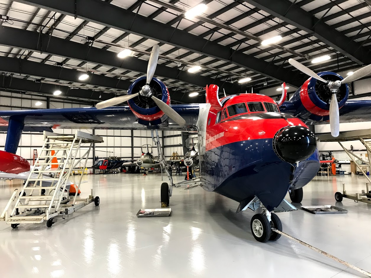
This is a picture I took when I was last on site of their awesome HU-16 flying boat with some ITPS fleet aircraft in the background.
The Hawker Hunter is a former front line fighter and ground attack aircraft. It first flew in 1951 and nearly 2000 units were built. Hunters were flown by everyone from Singapore to Somalia. Its was finally retired from service in 2014 and it’s long service life is a testament to the excellence of the original design.
Giorgio Clementi, President of ITPS: “Over thirty Hunters are still operational with operators providing RED AIR services to US and other NATO air forces today. Ex Rhodesian AF and Lebanese AF aircraft were recently purchased for refurbishment and pressing into service. There is a Hawker Hunter resurgence going on which is remarkable for a second generation jet design. Sir Sidney Camm (of Hawker Hurricane fame) got it right again! ITPS’s 5th Generation. Surrogate Training Aircraft project involves a number of aerodynamic and avionics upgrades to the Hawker Hunter.”
We will provide more detail about ITPS’s 5th generation surrogate training aircraft in next month’s newsletter
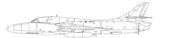
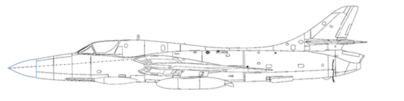
This is the original profile of the twin seat Hunter T-8
We were charged with creating a more modern looking radome, matching the loft of the fuselage at the radome interface and integrating with the 4 point attachment system.
One of the first things we had to do was to get a reasonable definition of the skin loft of the nose of the aircraft. ITPS arranged a commercial scanning company from Toronto to scan the forward fuselage. This does not generate a perfect representation but the data from the scan along with physical measurements will give us enough data to create the radome design.
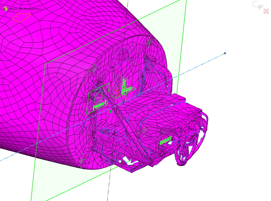
We created a parametric surface to match the scan of the skin as closely as possible
We then create a preliminary new radome surface that interfaces with the parametric skin loft at the interface plane. The aim is to match the tangency of the existing skin at the split line between the skin and the radome. Because of the new shape this was not achievable all the way around the interface but we got within a couple of degrees.
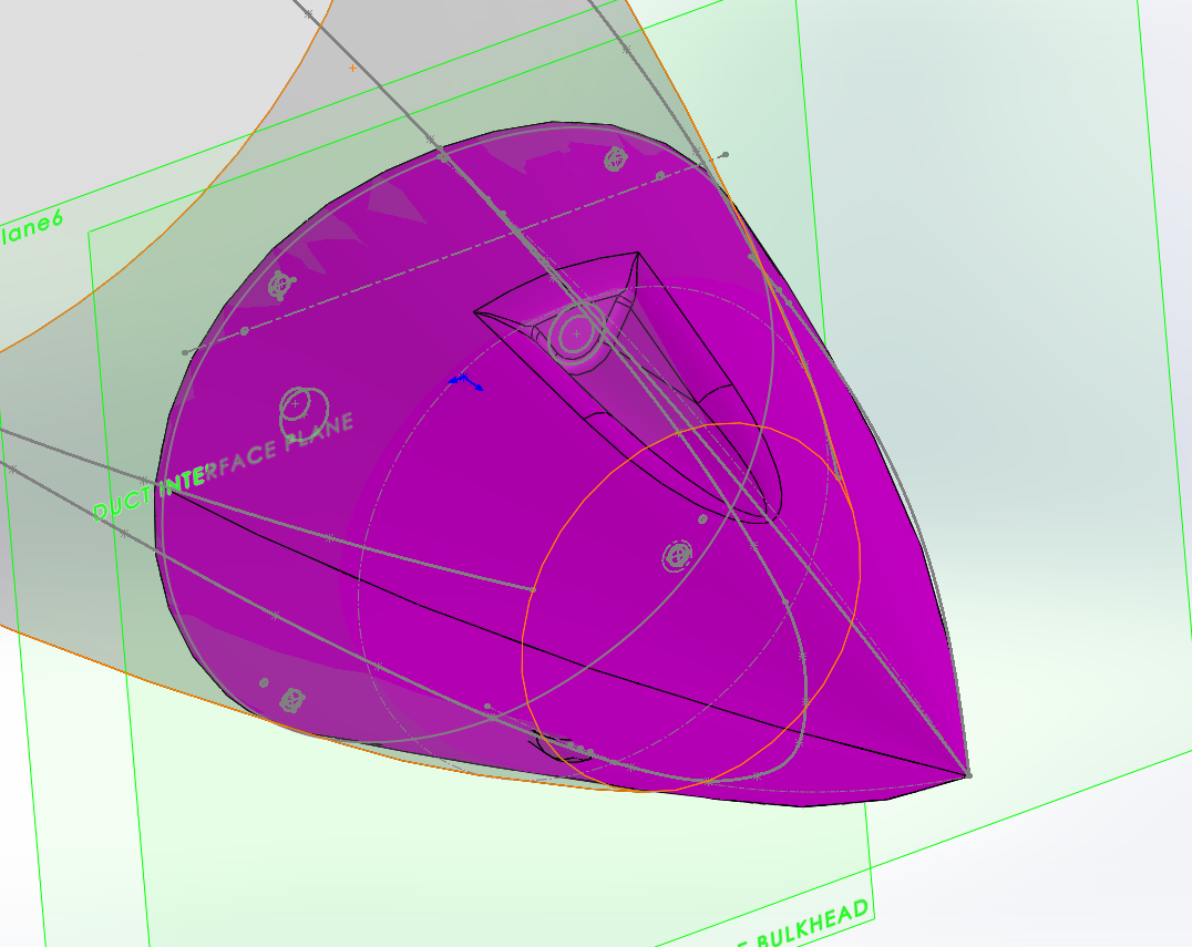
Note that this early loft of the new radome includes a feature in the top of the radome to match the original geometry that was later removed.
We can now check that the new radome looks good on the aircraft:
With the loft finalized and approved and the interface looking like a close match to the aircraft loft we could continue into the detailed design and analysis.
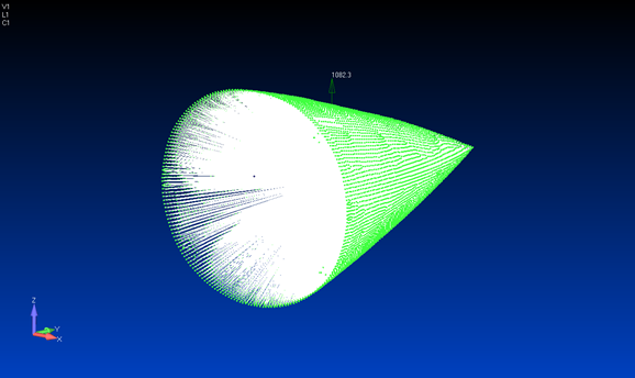
The loads for the radome were a little complicated. There is little specific information of this nature on the Hawker Hunter that is publicly available. However the aircraft documentation does contain the limitation of a 6g maneuver at Mach = 0.9.
One of the very nice aspects of working with ITPS is that their instructor pilots are all very qualified aircraft people. Dr Panos Vitsas from ITPS dived in to help us define the correct way to do this.
We generate a CL vs Mach number function for the wing planform, calculate a coefficient of lift and from the lift curve slope of the wing and derive an angle of attack – just over 9 degrees.
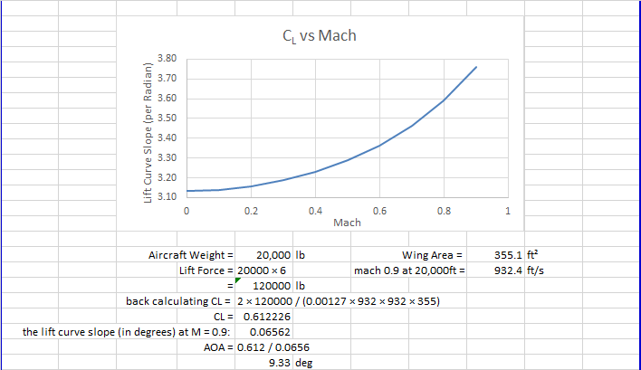
We then used some publicly available references to take our AOA and speed and the geometry of the radone to generate a normal force coefficient for the radome.
In the end we calculated a normal force of 1000lb, or a net normal pressure of 1.5psi, as the critical load case. We assumed this net normal force could apply in the radome in any orientation to the aircraft x -axis. A 9deg sideslip at Mach = 0.9 is a little conservative……but conservative is better than the alternative.
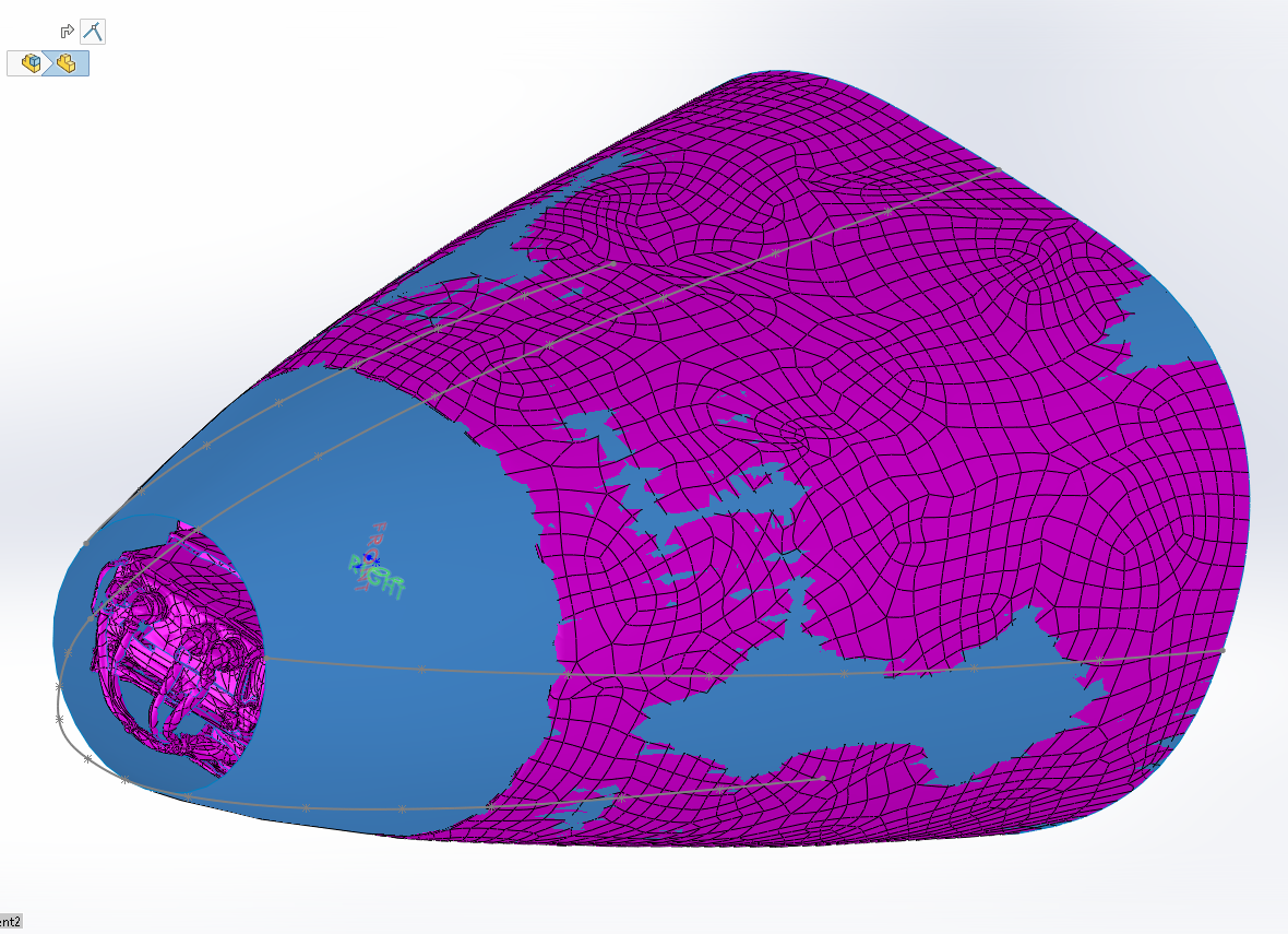
Using our best practice for composite finite element modelling (see earlier articles!) we created a Finite Element model. Note the feature in the upper surface is now removed, but we did not extend the cored region into this area. This is conservative and quicker to complete

In order to apply the load the structure I did a useful ‘cheat’.
I grabbed all of the nodes in the model and created a new RBE3 element with a node at the center of the new RBE 3 element.
Using this method of load application the load direction could also easily be changed.
To give complete disclosure, I also ran some cases with the load applied as a net pressure over one side of the radome and the model general response was similar to my ‘cheat’ approach.
In any case, in an analysis like this, where the loads contain overlapping assumptions we always look for healthy margins of safety.
The model was restrained to simulate the attachment to the aircraft and the model ran with no errors.
As we ran the model at limit level load, and the structure was to be all carbon fiber we used a limit level strain allowable of 3000microstrain. This implies an ultimate strain limit of 4500microstrain.
From our own reference text (Section 4.1.6 of our structures textbook) we recommend an open hole compression allowable of 4000microstrain for CFC.
In this case we used a larger value for two reasons. We would only be employing quasi-isotropic laminates and the 4000microstrain value is good for a mixture of laminate types and is conservative for quasi isotropic. The 4500microstrain limit is a no growth damage tolerance strain limit, as the radome is not primary structure, does not need to be damage tolerant and so strictly need not adhere to no growth strain limits.
As these ex-military aircraft are not flown under a normal type certificate we have more leeway in making these kind of value judgements. In any case everything we do still has to be justified and safe.
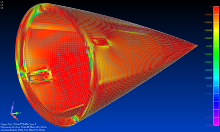
The static analysis results looked like this:
Laminate Strain:
Core stress:

Laminate strain and core stress gave us acceptable margins. Note that we only approach the strain limits at high Kt features. See the previous article as to why this is still indicative of high margins of safety. We ran the model for linear buckling and a got a nice high eigenvalue for the first buckling mode. We extracted the interface loads and checked the attachments and the joints.
As we were happy we went on to create the drawing:

and handed the drawing over to our manufacturing partner – Cynergy Composites
As this article is running long we will cover the manufacture and fitting of the radome onto the aircraft, some material and process issues and more about ITPS in the next issue.
For me, manufacturing and installation is the most interesting part of the work. Working with a good manufacturing partner makes the life of the engineer much easier and if the engineer is doing their job properly a large part of the design will be based on input from manufacturing.
A good manufacturing partner makes the difference between success and failure
Comment On This Post