
A version of this article first appeared in the October 2019 edition of our free newsletter, to subscribe click here
We have been finite element modeling composite structure since we started in 2008 and I have been creating finite element models of composite and metallic structure for over 25 years.
We have settled into a way of modeling composite structure that we believe is effective and relatively simple. Well, to us it seems simple because we have been doing it for a long time.
I am interested to hear if you think there are any better ways to model composite structure or a particular problem with the way we are modeling.
We use FEMAP to mesh the structure and the NxNASTRAN solver.
We have run benchmark tests against MscNASTRAN and other commercial solvers and for the models we have run there is little to no difference in the solution for linear static runs. If you have a different experience, please let us know.
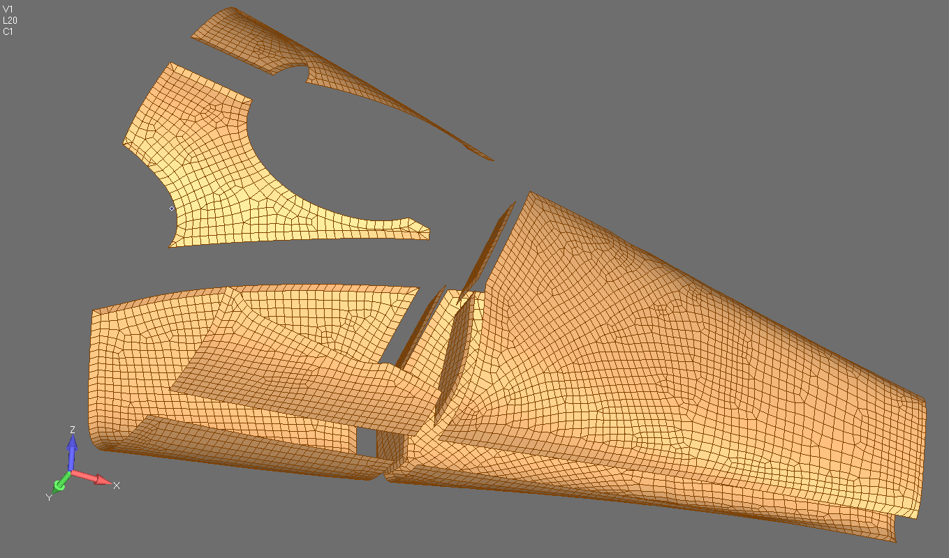
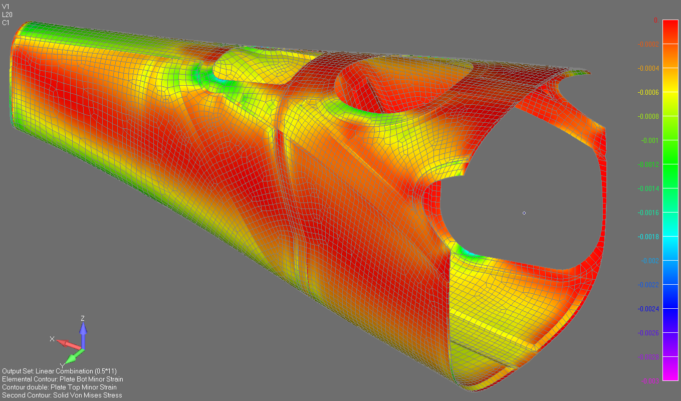
The general substantiation approach we use is the laminate strain approach. We don’t define global plies in the FE model as we have no specific interest in the behavior of an individual ply. We care about the surface strains of the laminate. Assuming a linear strain distribution through the thickness of the laminate one of the surfaces must be critical.
Where there is core we model the core using isotropic brick and wedge elements. Even where we have honeycomb core. This Is because the shear stiffness of the core perpendicular to the face of the laminate is the primary driver for stiffness behavior. We are aware this is an approximation but in extensive testing and correlation exercises we have not detected that this approximation is driving any significant inaccuracies.
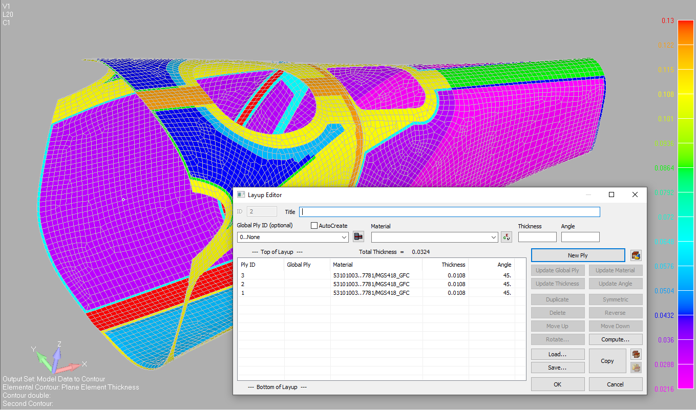
Where possible we tailor the thickness of each ply to the real world thickness of the ply stack. The average ply thickness does vary based on the number of plies in the laminate. When our clients are able to we set up test panels with different numbers of plies, cure them and measure them to have a good definition of how the average ply thickness varies with the thickness of the laminate and we modify the ply thicknesses for each laminate depending on the total number of plies in the stack.
As the out of plane stiffness is proportional to the square of the thickness this can significantly effect both the strain levels of uncored laminate subjected to out of plane bending and the results from the buckling solution. It is worth spending some effort to ensure your ply thickness values are as accurate as possible.
If in doubt the thickness per ply should be conservatively under estimated from the available data. The ply thickness used for normalization in the AGATE and NCAMP databases can be used. However we have found significant differences between this thickness value and the measured values in real life. As the normalized young’s modulus value in published material databases is based on the normalized ply thickness you would think it would be good to us both. Well, the answer to this issue is ‘it depends’
As the out of plane stiffness of the laminate varies linearly with the Young’s modulus values, but varies with the square of the thickness if there is a large difference between the measured ply thickness and the normalized ply thickness you can get some differences (inaccuracies) in the response of your finite element model if the standard database or vendor values are used without appropriate due diligence.
The variance of the normalized thickness value in these databases also affects the derived Young’s modulus values at the normalized thickness. These values can be used but should always be replaced with actual values from your in house measurements when they are available.
A last note on ply thicknesses. If unidirectional tape is employed in your design the nesting behavior and therefore the ply thickness varies with the mix of orientations in the ply stack. The ease at which the plies can interface with each other and reduce overall thickness is different between stack with all plies oriented in the 0 degree orientation and mixed 0 and 90 degree orientation
In the end how finely you generate the input data for your model depends on the application and the type of structure you are analyzing. If you are getting the last ounce of weight out of highly optimized primary structure in a certification program you need the best quality data you can generate. If you are in initial sizing or examining an unoptimized modification you have more leeway with the quality of your input data.
Note on sources of materials data.
Unlike metals there is no unimpeachable source for composite and core material data. Until your project compiles a comprehensive set of internally generated material the engineer is left with a patchwork of AGATE, NCAMP, vendor, borrowed and internally generated data.
In this circumstance, the engineer has to trust his experience and judgement to select and generate the best possible material data given the circumstances.
Note on environmental conditions.
It is conventional to use the room temperature composite material data in the finite element model. The reason for this is that for larger scale testing environmental effects are accounted for with load factors and the test article remains at room temperature. Room temperature material data is used to give you the best correlation to your strains recorded on test.
It is acceptable to use the room temperature values for core material properties as well. It is worth noting that specific hot wet strength values for core is not required. Indeed it is tacitly acknowledged that foam core and nomex honeycomb core does not maintain strength under extreme environmental conditions and the quality of the facing laminates is key to the longevity of cored structure. Even with this risk, part 23 cored aircraft structures have proven to be durable and reliable in service. However cored composite structure is not normally used in part 25 primary structure.
Note on tension and compression material properties
In typical composite material lamina data the different values for young modulus in compression and tension is recorded. For a finite element model using a linear material model the average of the tension and compression Young’s modulus values can be used.
Part 2 in next month’s newsletter.
Comment On This Post