A version of this article first appeared in the November 2019 edition of our free newsletter, to subscribe click here
Authors note: I started this series of articles in the last issue of the newsletter because the issues in the first article are questions that we are often asked. In this episode we go into the details of meshing cored features. These issues are less well known about and we are rarely asked about them. But these issues can have as great or greater effect than the material idealization we covered in the first episode in this series.
In the last part we looked at the material data and how to use it in your finite element model. In truth you need not use a finite element model. The same principles – surveying and using the best material data possible, using room temperature stiffness values, taking the average of compression and tension Young’s modulus, creating a local laminate strain value for comparison with worst case strain limits can all be done in a hand analysis as well.
We often use hand analysis for preliminary sizing – a wing is just a box beam carrying shear, bending and torsion and you can do good basic sizing work without a finite element model.
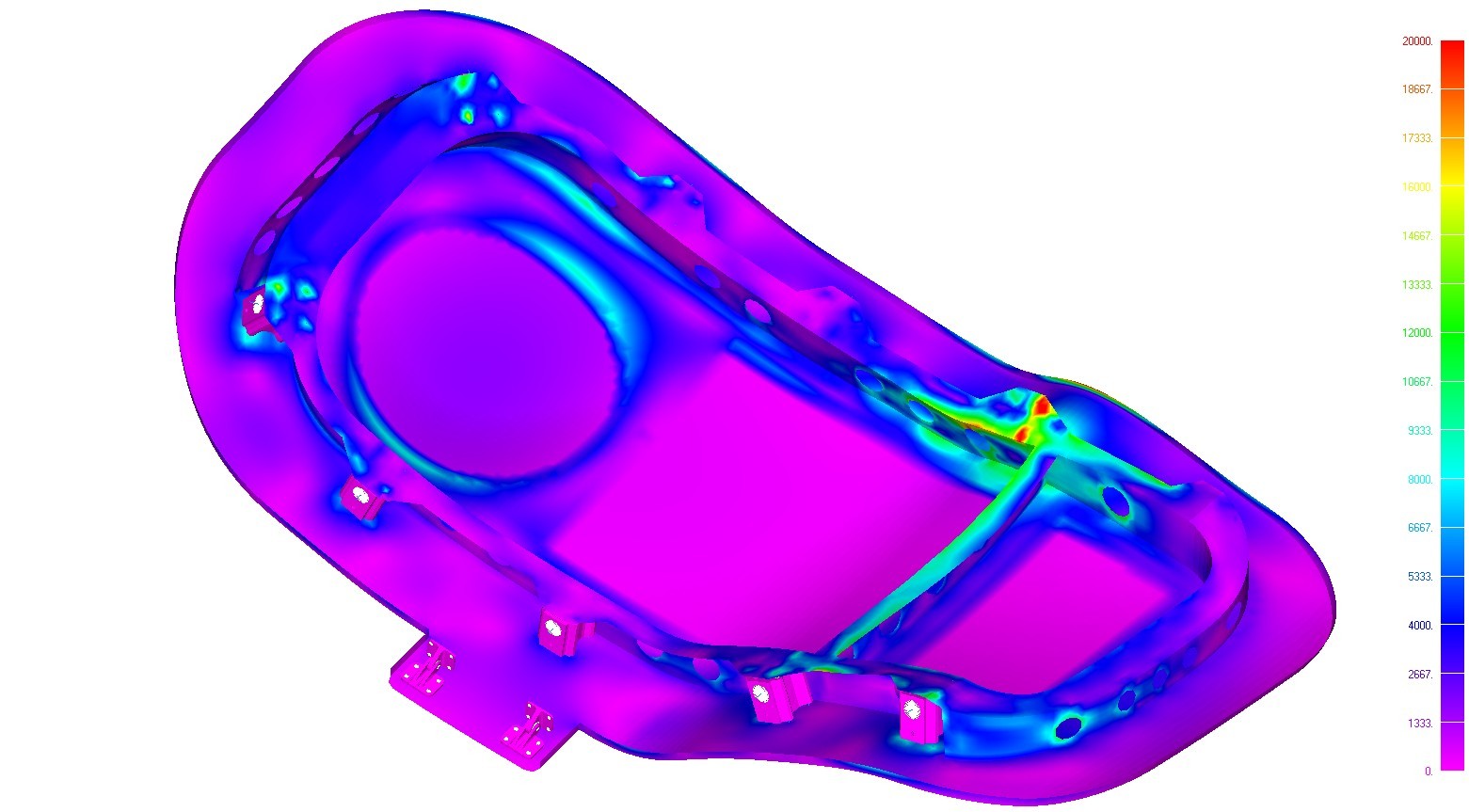
When you create your finite element model in the way we recommend – laminate plate elements for solid laminate and facing plies and solid brick or wedge elements for core you can spend a lot of time making the model a ‘perfect’ representation of the local laminate geometry.
This is a laudable approach to take but will likely exceed your budget and schedule. So what reasonable approximations can be taken, while keeping the model representative and allow you to create your mesh in a reasonable time?
You need to expend the least work for the least excessive conservatism and of course you should avoid the introduction of any optimistic aspect or feature to your modeling.
Optimism, cannot always be avoided but it should always be quantified and understood.
And many conservatisms can combine to render the model results so pessimistic that they drive excessive weight into the structure.
There is a middle ground of economy and accuracy that we have to aim for and a measure of fit for purpose we have to achieve.
No model is flawless; it is impossible to take an analog world and model it perfectly in the digital domain. Imperfection is the unavoidable norm and the magnitude and nature of the imperfection must be understood.
Understanding the level of inaccuracy is the purpose of correlating your test strains, failure load levels and failure modes between your testing and your analysis models. In the end you do have to achieve a reasonable measure of accuracy to validate your analysis.
We will examine some of these ‘economic’ measures below and their impact on the model results.
Where do the nodes go and what element offsets do you use?
For solid laminates and OML facing plies we place the nodes on the OML surface and offset the laminate plate elements by half of the thickness so the outer surface of the laminate plate element sits on the outer surface of the part.
That is relatively straightforward.
When it comes to cored regions it is not quite as simple.
There are three options of declining complexity and increasing conservatism (decreasing accuracy). The level of conservatism relies on the configuration of the cored laminate.
Option 1: The ‘Perfect Model’
Nodes positioned to define the core correctly

For this option the outer nodes have to be offset by the thickness of the outer plies, and the elements offset by half of their thickness towards the OML.
The inner plies over the core have to be offset by half of their thickness towards the IML of the laminate.
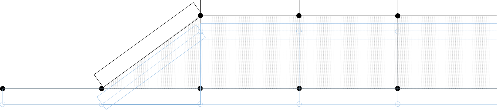
Option 2: The ‘Lazyboy’
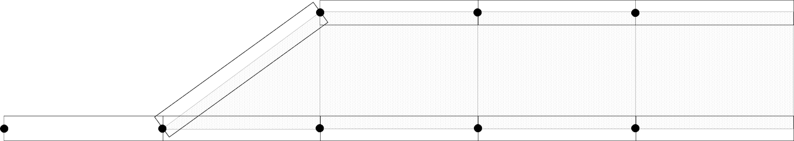
Outer nodes on the OML, inner nodes offset by the core thickness. No laminate plate offsets
Option 3: ‘Captain Conservative
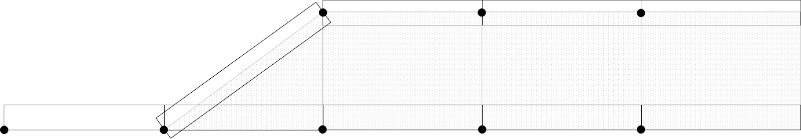
As option 2, but outer plies offset so the outer surface of the elements sit on the loft OML.
How do the results from these three different modeling techniques vary?
Well – the in plane stiffness will be ‘identical’ (with a caveat we will go into in a later episode) but the out of plane stiffness will vary.
The bending stiffness is expressed by EI (or D11 of the ABD matrix). However we will assume that E is constant across all of the examples. A comparison of the I (second moment of area values) is shown below for a range of cored laminate configurations
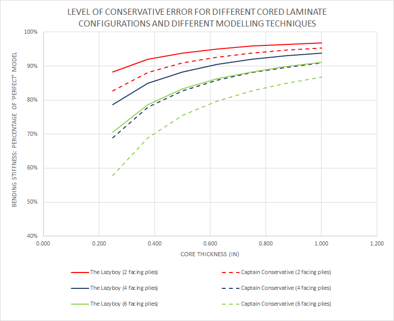
It can be concluded that for thinner core and thicker facing plies the ‘captain conservative’ approach will be excessively conservative but for thinner facing plies over relatively thick core it is acceptable.
The Lazyboy shows greater accuracy for all configurations – so why not use the lazyboy approach?
In some circumstances it may be acceptable to use the lazyboy, but there are common situations where it may start to yield optimistic results.
If you consider the skin of a box beam (wing). By allowing the OML elements to sit outside of the geometric OML of the wing section you are allowing a small increase in the bending stiffness of the wing, this is turn will slightly under predict the local loads.
This may be a small difference but in the creation of larger scale FE models you try to avoid any optimism in the stiffness and loads. If you introduce optimism at that level it will ‘infect’ all of the results of the model at the larger scale and the local level, it will also affect the aircraft level loads when aeroelasticity is accounted for.
Lazy Boy overlaid on the ‘Perfect’ Idealization

The Captain Conservative approach does have a small amount of this effect as the inner plies of the laminate are further away from the neutral axis (but the sum of half the thickness of the inner and outer plies combined). This is not as critical as the inner plies of the cored laminate do not tend to attract as much moment reaction loads as the outer plies.
Taking a quick example (if you want the working out let me know) taking a sample wing box section with a 16in chord, a 6in depth and considering the skins alone. Assuming a .048in ply thickness over a 0.5in core. If the inner plies are offset the thickness of the ply towards the OML the bending stiffness of the section is overestimated by 1.5%. However, this error is reduced for the overall wing section when you consider the effect of the spar caps and the spar webs. So the global spanwise strains and deflections may be reduced by, say 1%, the local out of plane stiffnesses and strains will be 10% conservative.
For this reason we use ‘Captain Conservative’ as our preferred method in larger scale finite element models. We will avoid optimism at the internal load distribution in favor of additional conservatism at the local level.
Captain Conservative overlaid on the ‘Perfect’ Idealization
So what does Captain Conservative do to your analysis? The answer to that is straight forward. You over-predict local bending strains and the onset of buckling.
These effects are over-predicted by the conservatism ratio of the local bending stiffness compared to the local bending stiffness of the ‘perfect’ solution.
If you wish you can account for these effects at the final margin of safety by reducing the bending component of the applied load effects by this ratio.
If we can meet our weight target without taking account of these conservatisms ‘after the fact’ we will not account for them. In my experience of many tests of bonded, cored composite assemblies the failure mode is either driven directly by a cored panel buckle, or a secondary effect of a panel buckle – large out of plane loads created by the buckle failing its own integral structure or a bonded joint in peel.
If I can add in some residual buckling strength for panel buckling into my cored panels I will take that to the bank.
For mechanically fastened cored composite assemblies or uncored composite assemblies these issues are less critical – but should still make you a little nervous.
In the next issue we will look at how we model some common details in composite assemblies and the effect on the results..
Comment On This Post