17,005 Documents in our Technical Library
2459018 Total Downloads

Newest Additions

NASA-RP-1060 Subsonic Aircraft: Evolution and the Matching of Size to Performance
AA-CP-20212-001
AA-CP-20212-001
ADPO10769 Occurrence of Corrosion in Airframes
The purpose of this lecture is to provide an overview ...
MIL-STD-1759 Rivets and Rivet Type Fasteners Preferred for Design
The purpose of this book form standard is to provide ...
MIL-STD-810G Environmental Engineering Considerations and Laboratory Tests
This standard contains materiel acquisition program planning and engineering direction ...

naca-tn-2881

  • Version
  • 176 Downloads
  • 3.65 MB File Size
  • 1 File Count
  • January 17, 2017 Create Date
  • January 17, 2017 Last Updated
Scroll for Details

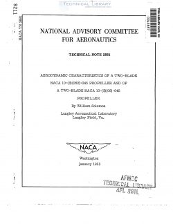
National Advisory Committee for Aeronautics, Technical Notes - Aerodynamic Characteristics of a Two Blade NACA 10-(3)(062)-045 Propeller and of a Two Blade NACA 10-(3)(08)-045 Propeller
As part of the investigation to determine the influence of blade—
section thickness ratio on propeller performance, tests were made in
the Langley 16-foot high-speed tunnel to determine the aerodynamic
characteristics of the two—blade NACA lO- (3)(O62)—Oh5 propeller and of
the two-blade NACA lO- (3)(o8)-0A5 propeller.

Data were obtained over a blade—angle range from 20° to 550 as
measured at the 0.75—radius station, the various constant values of
rotational speed used giving a range of advance ratio from 0.5 to 3.8.
Maximum efficiencies of the order of 91.5 to 92 percent were obtained
for the propellers. The propeller with the thinner airfoil sections
over the outboard portion of the blades, the NACA lo—(3)(o62)—oh5 pro—
peller, had lower losses at high tip speeds, the difference amounting
to about 5 percent at a helical tip Mach number of 1.10.

The aerodynamic characteristics of a series of lO—foot—diameter
propellers were investigated in the Langley 16—foot high—speed tunnel
in a comprehensive propeller research program. Having high—critical—
speed NACA 16— series airfoil sections (ref. 1), these propellers were
designed to have Betz minimum induced—energy—loss loading (ref. 2) for
a blade angle of #50 at the 0.7 radius When used as a four4b1ade pro-
peller operating at an advance ratio of approximately 2.1. The ultimate
purpose of the program was to determine the influence upon propeller
performance of propeller design factors and of compressibility; the pro—
peller tests reported herein form part of the investigation of the
effects of blade-section thickness ratio.

Propeller dynamometer.— A diagram showing the configuration for
these propeller tests with the 2000—horsepower dynamometer is shown in
figure 1. The test apparatus and thrust and torque measuring devices
are described in detail in reference 3.

Propeller blades.— The blades are of NACA 10—(3)(o62)-oh5 and
NACA lO—%352085-0E5 design which have designation numbers descriptive
of the propeller shape, size, and design aerodynamic characteristics.
The numerals of the first group give the diameter in feet; the numerals
within the first parentheses give the design lift coefficient, in tenths,
of the blade section at the 0.7 radius; the numerals within the second
parentheses give the thickness ratio at the 0.7 radius; and the last
group designates the solidity of one blade of the propeller at the
0.7 radius. Solidity is the ratio of the blade width at any radius to
the circumference of the circle traversed by that blade section. Blade-
form curves for these propellers are shown in figure 2. As can be seen,
the blades differ only in thickness ratio and, very slightly, in blade
angle; bladeewidth ratio and design lift coefficient are identical for
the two propellers.

FileAction
naca-tn-2881 Aerodynamic Characteristics of a Two Blade NACA 10-(3)(062)-045 Propeller and of a Two Blade NACA 10-(3)(08)-045 Prope.pdfDownload 

Comment On This Post

Your email address will not be published. Required fields are marked *

naca-tn-2881

  • Version
  • 176 Downloads
  • 3.65 MB File Size
  • 1 File Count
  • January 17, 2017 Create Date
  • January 17, 2017 Last Updated
Scroll for Details

National Advisory Committee for Aeronautics, Technical Notes - Aerodynamic Characteristics of a Two Blade NACA 10-(3)(062)-045 Propeller and of a Two Blade NACA 10-(3)(08)-045 Propeller

As part of the investigation to determine the influence of blade—
section thickness ratio on propeller performance, tests were made in
the Langley 16-foot high-speed tunnel to determine the aerodynamic
characteristics of the two—blade NACA lO- (3)(O62)—Oh5 propeller and of
the two-blade NACA lO- (3)(o8)-0A5 propeller.

Data were obtained over a blade—angle range from 20° to 550 as
measured at the 0.75—radius station, the various constant values of
rotational speed used giving a range of advance ratio from 0.5 to 3.8.
Maximum efficiencies of the order of 91.5 to 92 percent were obtained
for the propellers. The propeller with the thinner airfoil sections
over the outboard portion of the blades, the NACA lo—(3)(o62)—oh5 pro—
peller, had lower losses at high tip speeds, the difference amounting
to about 5 percent at a helical tip Mach number of 1.10.

The aerodynamic characteristics of a series of lO—foot—diameter
propellers were investigated in the Langley 16—foot high—speed tunnel
in a comprehensive propeller research program. Having high—critical—
speed NACA 16— series airfoil sections (ref. 1), these propellers were
designed to have Betz minimum induced—energy—loss loading (ref. 2) for
a blade angle of #50 at the 0.7 radius When used as a four4b1ade pro-
peller operating at an advance ratio of approximately 2.1. The ultimate
purpose of the program was to determine the influence upon propeller
performance of propeller design factors and of compressibility; the pro—
peller tests reported herein form part of the investigation of the
effects of blade-section thickness ratio.

Propeller dynamometer.— A diagram showing the configuration for
these propeller tests with the 2000—horsepower dynamometer is shown in
figure 1. The test apparatus and thrust and torque measuring devices
are described in detail in reference 3.

Propeller blades.— The blades are of NACA 10—(3)(o62)-oh5 and
NACA lO—%352085-0E5 design which have designation numbers descriptive
of the propeller shape, size, and design aerodynamic characteristics.
The numerals of the first group give the diameter in feet; the numerals
within the first parentheses give the design lift coefficient, in tenths,
of the blade section at the 0.7 radius; the numerals within the second
parentheses give the thickness ratio at the 0.7 radius; and the last
group designates the solidity of one blade of the propeller at the
0.7 radius. Solidity is the ratio of the blade width at any radius to
the circumference of the circle traversed by that blade section. Blade-
form curves for these propellers are shown in figure 2. As can be seen,
the blades differ only in thickness ratio and, very slightly, in blade
angle; bladeewidth ratio and design lift coefficient are identical for
the two propellers.

FileAction
naca-tn-2881 Aerodynamic Characteristics of a Two Blade NACA 10-(3)(062)-045 Propeller and of a Two Blade NACA 10-(3)(08)-045 Prope.pdfDownload 
17,005 Documents in our Technical Library
2459018 Total Downloads

Search The Technical Library

Newest Additions

NASA-RP-1060 Subsonic Aircraft: Evolution and the Matching of Size to Performance
AA-CP-20212-001
AA-CP-20212-001
ADPO10769 Occurrence of Corrosion in Airframes
The purpose of this lecture is to provide an overview ...
MIL-STD-1759 Rivets and Rivet Type Fasteners Preferred for Design
The purpose of this book form standard is to provide ...
MIL-STD-810G Environmental Engineering Considerations and Laboratory Tests
This standard contains materiel acquisition program planning and engineering direction ...