17,005 Documents in our Technical Library
2449545 Total Downloads

Newest Additions

NASA-RP-1060 Subsonic Aircraft: Evolution and the Matching of Size to Performance
AA-CP-20212-001
AA-CP-20212-001
ADPO10769 Occurrence of Corrosion in Airframes
The purpose of this lecture is to provide an overview ...
MIL-STD-1759 Rivets and Rivet Type Fasteners Preferred for Design
The purpose of this book form standard is to provide ...
MIL-STD-810G Environmental Engineering Considerations and Laboratory Tests
This standard contains materiel acquisition program planning and engineering direction ...

naca-report-1333

  • Version
  • 146 Downloads
  • 1.40 MB File Size
  • 1 File Count
  • November 2, 2016 Create Date
  • November 2, 2016 Last Updated
Scroll for Details

National Advisory Committee for Aeronautics, Report - Attenuation in a Shock Tube Due to Unsteady Boundary Layer Action
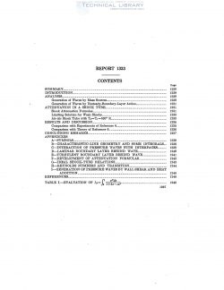
naca-report-1333-attenuation-in-a-shock-tube-due-to-unsteady-boundary-layer-action-1

A method is presented for obtaining the attenuation of a
shock wave in a shock tube due to the unsteady boundary layer
along the shock—tube walls. It is assumed that the boundary
layer is thin relative to the tube diameter and induces, one-
dimensional longitudinal pressure waves whose strength is
proportional to the vertical velocity at the edge of the boundary
layer. The contributions of the various regions in a shock
tube to shock attenuation are indicated.
The method is shown to be in reasonably good agreement with existing
experimental data.

A shock tube consists of a fluid at high pressure (region 4
of fig. 1 (a)) separated by a diaphragm from a fluid at low
pressure (region 1). When the diaphragm bursts, a shock
wave propagates into region 1 while an expansion wave
propagates into region 4. A time-distance plot of these
waves under ideal conditions is indicated in figure 1 (b).
Regions 2 and 3 have the same velocity and pressure but
have different temperatures. The interface between regions
2 and 3 is referred to as a contact surface. The analysis of
the flow for perfect fluids is straight—forward (see, for ex-
ample, ref. 1). In an actual shock tube, however, viscosity
and heat conduction cannot be ignored. These lead to a
boundary layer along the walls of the shock tube, as indi-
cated in figure 1 (c). The boundary layer introduces non-
uniformities into the shock tube. Analytical studies of this
boundary layer are presented in references 2 to 6. One of
the important consequences of the wall boundary layer is
that it generates weak pressure waves which catch up with
and attenuate the shock wave propagating into region 1.
This attenuation has been studied experimentally and
analytically in the work of references 1, 4, 5, and 6, and is
the subject of the present report. It is assumed that the
boundary layer is thin relative to the shock-tube diameter.
This is a practical restriction, since most shock tubes are
designed so that the core of potential flow is relatively
uniform in order to permit aerodynamic tests.

A few remarks concerning previous shock-wave-attenuation
analyses are appropriate. In reference 4, the coordinate
system is defined so that the shock wave is stationary. The
flow between the shock wave and the contact surface is
considered as a one—dimensional steady flow so that at each
instant the mass flow through the shock wave equals the
mass flow at the contact surface. If the mass flow at the
contact surface is known at each instant, the correspond-
ing shock strength can be found. The mass flow at the
contact surface is determined from the local boundary-layer
displacement thickness and free-stream conditions corre-
sponding to an unattenuated shock However, it can be
shown that free-stream conditions do not remain constant
at the contact surface (because of perturbations induced by
the boundary layer).

FileAction
naca-report-1333 Attenuation in a Shock Tube Due to Unsteady Boundary Layer Action.pdfDownload 

Comment On This Post

Your email address will not be published. Required fields are marked *

naca-report-1333

  • Version
  • 146 Downloads
  • 1.40 MB File Size
  • 1 File Count
  • November 2, 2016 Create Date
  • November 2, 2016 Last Updated
Scroll for Details

National Advisory Committee for Aeronautics, Report - Attenuation in a Shock Tube Due to Unsteady Boundary Layer Action

naca-report-1333-attenuation-in-a-shock-tube-due-to-unsteady-boundary-layer-action-1

A method is presented for obtaining the attenuation of a
shock wave in a shock tube due to the unsteady boundary layer
along the shock—tube walls. It is assumed that the boundary
layer is thin relative to the tube diameter and induces, one-
dimensional longitudinal pressure waves whose strength is
proportional to the vertical velocity at the edge of the boundary
layer. The contributions of the various regions in a shock
tube to shock attenuation are indicated.
The method is shown to be in reasonably good agreement with existing
experimental data.

A shock tube consists of a fluid at high pressure (region 4
of fig. 1 (a)) separated by a diaphragm from a fluid at low
pressure (region 1). When the diaphragm bursts, a shock
wave propagates into region 1 while an expansion wave
propagates into region 4. A time-distance plot of these
waves under ideal conditions is indicated in figure 1 (b).
Regions 2 and 3 have the same velocity and pressure but
have different temperatures. The interface between regions
2 and 3 is referred to as a contact surface. The analysis of
the flow for perfect fluids is straight—forward (see, for ex-
ample, ref. 1). In an actual shock tube, however, viscosity
and heat conduction cannot be ignored. These lead to a
boundary layer along the walls of the shock tube, as indi-
cated in figure 1 (c). The boundary layer introduces non-
uniformities into the shock tube. Analytical studies of this
boundary layer are presented in references 2 to 6. One of
the important consequences of the wall boundary layer is
that it generates weak pressure waves which catch up with
and attenuate the shock wave propagating into region 1.
This attenuation has been studied experimentally and
analytically in the work of references 1, 4, 5, and 6, and is
the subject of the present report. It is assumed that the
boundary layer is thin relative to the shock-tube diameter.
This is a practical restriction, since most shock tubes are
designed so that the core of potential flow is relatively
uniform in order to permit aerodynamic tests.

A few remarks concerning previous shock-wave-attenuation
analyses are appropriate. In reference 4, the coordinate
system is defined so that the shock wave is stationary. The
flow between the shock wave and the contact surface is
considered as a one—dimensional steady flow so that at each
instant the mass flow through the shock wave equals the
mass flow at the contact surface. If the mass flow at the
contact surface is known at each instant, the correspond-
ing shock strength can be found. The mass flow at the
contact surface is determined from the local boundary-layer
displacement thickness and free-stream conditions corre-
sponding to an unattenuated shock However, it can be
shown that free-stream conditions do not remain constant
at the contact surface (because of perturbations induced by
the boundary layer).

FileAction
naca-report-1333 Attenuation in a Shock Tube Due to Unsteady Boundary Layer Action.pdfDownload 
17,005 Documents in our Technical Library
2449545 Total Downloads

Search The Technical Library

Newest Additions

NASA-RP-1060 Subsonic Aircraft: Evolution and the Matching of Size to Performance
AA-CP-20212-001
AA-CP-20212-001
ADPO10769 Occurrence of Corrosion in Airframes
The purpose of this lecture is to provide an overview ...
MIL-STD-1759 Rivets and Rivet Type Fasteners Preferred for Design
The purpose of this book form standard is to provide ...
MIL-STD-810G Environmental Engineering Considerations and Laboratory Tests
This standard contains materiel acquisition program planning and engineering direction ...