17,005 Documents in our Technical Library
2464464 Total Downloads

Newest Additions

NASA-RP-1060 Subsonic Aircraft: Evolution and the Matching of Size to Performance
AA-CP-20212-001
AA-CP-20212-001
ADPO10769 Occurrence of Corrosion in Airframes
The purpose of this lecture is to provide an overview ...
MIL-STD-1759 Rivets and Rivet Type Fasteners Preferred for Design
The purpose of this book form standard is to provide ...
MIL-STD-810G Environmental Engineering Considerations and Laboratory Tests
This standard contains materiel acquisition program planning and engineering direction ...

naca-rm-l7h26

  • Version
  • 151 Downloads
  • 707.99 KB File Size
  • 1 File Count
  • March 14, 2017 Create Date
  • March 14, 2017 Last Updated
Scroll for Details

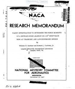
National Advisory Committe for Aeronautics, Research Memorandum - Flight Investigation to Determine the Hinge Moments of a Beveled-Edge Aileron on a 45° Sweptback Wing at Transonic and Low Supersonic Speeds
The standard RM-l stability and control research pilotless
aircraft consists of a sharp-nose cylindrical body of fineness
ratio 22 .7 equipped with cruciform wings and cruciform fine.
The wings and fins are of constant chord NADA 65-010 airfoil
section normal to the leading edge. Figure l is a sketch of the
RM-l model showing its over-ell dimensions; and figure 2 is a
photograph of a model, eauipped with a booster rocket, mounted ,
on its launching rack at the 50° launching angle. The model,
booster, and launching equipment are completely described in
reference 1..

Two diametrically opposite wings are" equipped with, ailerons .
Figure 3 is a sketch showing the detail dimensions of the wing and
aileron. The ailerons are 0.10011 and O.33(b/2) , They have an -
overhang balance of 0.52ca and a 200‘ beveled trailing edge. The
servomechenisms are set to limit the aileron travel to approximately
+100 deflection.

The electromagnetic servomechanisms used to actuate the ailerons
function as a flicker-type control, that is, the ailerons are
deflected in either one extreme position or the other at all times.
The sense of control deflection is determined by a roll-stabilization
automatic pilot, identical to the one described in reference 1,
except that the rate gyroscope was removed making the automatic pilot
a displacement response, flicker-type system.

The load calibration of the servomechanisms employed is presented
in figure it and is plotted as hinge moment against aileron deflection 5a-

For any given hinge moment the servomechanism was able to hold the
aileron at whatever deflection is shown.

Structural tests. were made after the flight on wings identical
to those used on the model to determine the torsional rigidity of the
wing. Torsional moments. were applied at the wing tip, and the
angular deflection of the midaileron chord parallel to the air stream
was measured relative to the center line of the model. These tests
show that the torsional stiffness of this laminated spruce wing was
equivalent to 230 inch-pounds per degree.

FileAction
naca-rm-l7h26 Flight Investigation to Determine the Hinge Moments of a Beveled-Edge Aileron on a 45° Sweptback Wing at.pdfDownload 

Comment On This Post

Your email address will not be published. Required fields are marked *

naca-rm-l7h26

  • Version
  • 151 Downloads
  • 707.99 KB File Size
  • 1 File Count
  • March 14, 2017 Create Date
  • March 14, 2017 Last Updated
Scroll for Details

National Advisory Committe for Aeronautics, Research Memorandum - Flight Investigation to Determine the Hinge Moments of a Beveled-Edge Aileron on a 45° Sweptback Wing at Transonic and Low Supersonic Speeds

The standard RM-l stability and control research pilotless
aircraft consists of a sharp-nose cylindrical body of fineness
ratio 22 .7 equipped with cruciform wings and cruciform fine.
The wings and fins are of constant chord NADA 65-010 airfoil
section normal to the leading edge. Figure l is a sketch of the
RM-l model showing its over-ell dimensions; and figure 2 is a
photograph of a model, eauipped with a booster rocket, mounted ,
on its launching rack at the 50° launching angle. The model,
booster, and launching equipment are completely described in
reference 1..

Two diametrically opposite wings are" equipped with, ailerons .
Figure 3 is a sketch showing the detail dimensions of the wing and
aileron. The ailerons are 0.10011 and O.33(b/2) , They have an -
overhang balance of 0.52ca and a 200‘ beveled trailing edge. The
servomechenisms are set to limit the aileron travel to approximately
+100 deflection.

The electromagnetic servomechanisms used to actuate the ailerons
function as a flicker-type control, that is, the ailerons are
deflected in either one extreme position or the other at all times.
The sense of control deflection is determined by a roll-stabilization
automatic pilot, identical to the one described in reference 1,
except that the rate gyroscope was removed making the automatic pilot
a displacement response, flicker-type system.

The load calibration of the servomechanisms employed is presented
in figure it and is plotted as hinge moment against aileron deflection 5a-

For any given hinge moment the servomechanism was able to hold the
aileron at whatever deflection is shown.

Structural tests. were made after the flight on wings identical
to those used on the model to determine the torsional rigidity of the
wing. Torsional moments. were applied at the wing tip, and the
angular deflection of the midaileron chord parallel to the air stream
was measured relative to the center line of the model. These tests
show that the torsional stiffness of this laminated spruce wing was
equivalent to 230 inch-pounds per degree.

FileAction
naca-rm-l7h26 Flight Investigation to Determine the Hinge Moments of a Beveled-Edge Aileron on a 45° Sweptback Wing at.pdfDownload 
17,005 Documents in our Technical Library
2464464 Total Downloads

Search The Technical Library

Newest Additions

NASA-RP-1060 Subsonic Aircraft: Evolution and the Matching of Size to Performance
AA-CP-20212-001
AA-CP-20212-001
ADPO10769 Occurrence of Corrosion in Airframes
The purpose of this lecture is to provide an overview ...
MIL-STD-1759 Rivets and Rivet Type Fasteners Preferred for Design
The purpose of this book form standard is to provide ...
MIL-STD-810G Environmental Engineering Considerations and Laboratory Tests
This standard contains materiel acquisition program planning and engineering direction ...