17,005 Documents in our Technical Library
2463371 Total Downloads

Newest Additions

NASA-RP-1060 Subsonic Aircraft: Evolution and the Matching of Size to Performance
AA-CP-20212-001
AA-CP-20212-001
ADPO10769 Occurrence of Corrosion in Airframes
The purpose of this lecture is to provide an overview ...
MIL-STD-1759 Rivets and Rivet Type Fasteners Preferred for Design
The purpose of this book form standard is to provide ...
MIL-STD-810G Environmental Engineering Considerations and Laboratory Tests
This standard contains materiel acquisition program planning and engineering direction ...

naca-rm-e6l04

  • Version
  • 125 Downloads
  • 1.04 MB File Size
  • 1 File Count
  • March 14, 2017 Create Date
  • March 14, 2017 Last Updated
Scroll for Details

National Advisory Committe for Aeronautics, Reseach Memorandum - Performance of the 19XB 10 Stage Axial-Flow Compressor
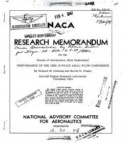
The 19XB compressor, which replaces the 193 compressor (refer-
ence l) and has the same length and diameter as the 19XB compressor,
was designed with 10 stagetho deliver 50 pounds of air per second
for a pressure ratio of 4.17 at.an equivalent speed of 17,000 rpm;
the 19BXB was designed with six stages for a pressure ratio of 2.7 at
the same weight flow and speed as the 19XBcompressor. The performs
ance characteristics of the new compressor were determined at the
NASA Cleveland laboratory at the request of the Bureau of Aeronautics,
Navy Department.

Results are presented of the investigation made to evaluate the
over-all performance of the compressor, the effects of possible
leakage past the rotor rear air seal, the effects of inserting instru-
ments in each row of stator blades and in the first row of outlet
guide vanes, and the effects of changing the temperature and the pres—
sure of the inlet air. The results of the interstage surveys are also
presented.

The construction or the lorstage axialaflow compresson used in
the 19XB Jet~propufsion unit is similar to that of the six stage
19XB compressor described in reference 1. A photograph of the assem-
bled lO-stage compressor with the upper half of the casing removed "
is shown in figure 1. A cross-sectional drawing of the compressor
with the principal dimensions is given in figure 2; the path of pos-
sible air leakage past the rotor rear air seal is also shown.

The cast-aluminum inlet section and the discharge section are
the same as those of the 193 compressor (reference 1). Fairing
inserts were installed on the inner and outer.walls after the outlet
guide vanes to give a straight annular passage for the discharge
measuring station. The split stator casing differs from that of the
19XB compressor only in the number and spacing of the circumferential
grooves for the stator-blade outer shrouds. The rotor of the
compressor is constructed in four sections, whereas that of the
19XB was machined from a single aluminum-alloy forging. The forward
section of the 19XB rotor consists of seven blade rows machined from
a single aluminum—alloy forging. The rear section, which was bolted
to the aluminum section, consists of three disks, each machined from
a separate steel forging. A steel sleeve pressed on the aluminum -
section of the rotor forms the front bearing Journal. The rotor is
rigidly connected to the drive shaft, which is supported by the two
rear bearings. In the Jet—engine installation, the rigid connection
permits the thrust of the compressor to oppose that of the turbine
and thus relieves part of the load on the thrust bearing.

The design of the blading for the lQXB compressor stresses
simplicity and ease of manufacture rather than any particular airfoil
shape. As received from the manufacturer, all the blading of the
compressor was nicked and pitted from_previous running of the complete
jet engine, but-the tests were made with these blemishes. Most of the
blade angles had been changed from their original design values by
plastically deforming the metal at a point approximately oneefourth
inch from the root of the blades. Table I lists the design specifi-
cations (including these-deformations) for all the compressor blading.

.

FileAction
naca-rm-e6l04 Performance of the 19XB 10 Stage Axial-Flow Compressor.pdfDownload 

Comment On This Post

Your email address will not be published. Required fields are marked *

naca-rm-e6l04

  • Version
  • 125 Downloads
  • 1.04 MB File Size
  • 1 File Count
  • March 14, 2017 Create Date
  • March 14, 2017 Last Updated
Scroll for Details

National Advisory Committe for Aeronautics, Reseach Memorandum - Performance of the 19XB 10 Stage Axial-Flow Compressor

The 19XB compressor, which replaces the 193 compressor (refer-
ence l) and has the same length and diameter as the 19XB compressor,
was designed with 10 stagetho deliver 50 pounds of air per second
for a pressure ratio of 4.17 at.an equivalent speed of 17,000 rpm;
the 19BXB was designed with six stages for a pressure ratio of 2.7 at
the same weight flow and speed as the 19XBcompressor. The performs
ance characteristics of the new compressor were determined at the
NASA Cleveland laboratory at the request of the Bureau of Aeronautics,
Navy Department.

Results are presented of the investigation made to evaluate the
over-all performance of the compressor, the effects of possible
leakage past the rotor rear air seal, the effects of inserting instru-
ments in each row of stator blades and in the first row of outlet
guide vanes, and the effects of changing the temperature and the pres—
sure of the inlet air. The results of the interstage surveys are also
presented.

The construction or the lorstage axialaflow compresson used in
the 19XB Jet~propufsion unit is similar to that of the six stage
19XB compressor described in reference 1. A photograph of the assem-
bled lO-stage compressor with the upper half of the casing removed "
is shown in figure 1. A cross-sectional drawing of the compressor
with the principal dimensions is given in figure 2; the path of pos-
sible air leakage past the rotor rear air seal is also shown.

The cast-aluminum inlet section and the discharge section are
the same as those of the 193 compressor (reference 1). Fairing
inserts were installed on the inner and outer.walls after the outlet
guide vanes to give a straight annular passage for the discharge
measuring station. The split stator casing differs from that of the
19XB compressor only in the number and spacing of the circumferential
grooves for the stator-blade outer shrouds. The rotor of the
compressor is constructed in four sections, whereas that of the
19XB was machined from a single aluminum-alloy forging. The forward
section of the 19XB rotor consists of seven blade rows machined from
a single aluminum—alloy forging. The rear section, which was bolted
to the aluminum section, consists of three disks, each machined from
a separate steel forging. A steel sleeve pressed on the aluminum -
section of the rotor forms the front bearing Journal. The rotor is
rigidly connected to the drive shaft, which is supported by the two
rear bearings. In the Jet—engine installation, the rigid connection
permits the thrust of the compressor to oppose that of the turbine
and thus relieves part of the load on the thrust bearing.

The design of the blading for the lQXB compressor stresses
simplicity and ease of manufacture rather than any particular airfoil
shape. As received from the manufacturer, all the blading of the
compressor was nicked and pitted from_previous running of the complete
jet engine, but-the tests were made with these blemishes. Most of the
blade angles had been changed from their original design values by
plastically deforming the metal at a point approximately oneefourth
inch from the root of the blades. Table I lists the design specifi-
cations (including these-deformations) for all the compressor blading.

.

FileAction
naca-rm-e6l04 Performance of the 19XB 10 Stage Axial-Flow Compressor.pdfDownload 
17,005 Documents in our Technical Library
2463371 Total Downloads

Search The Technical Library

Newest Additions

NASA-RP-1060 Subsonic Aircraft: Evolution and the Matching of Size to Performance
AA-CP-20212-001
AA-CP-20212-001
ADPO10769 Occurrence of Corrosion in Airframes
The purpose of this lecture is to provide an overview ...
MIL-STD-1759 Rivets and Rivet Type Fasteners Preferred for Design
The purpose of this book form standard is to provide ...
MIL-STD-810G Environmental Engineering Considerations and Laboratory Tests
This standard contains materiel acquisition program planning and engineering direction ...