17,005 Documents in our Technical Library
2464368 Total Downloads

Newest Additions

NASA-RP-1060 Subsonic Aircraft: Evolution and the Matching of Size to Performance
AA-CP-20212-001
AA-CP-20212-001
ADPO10769 Occurrence of Corrosion in Airframes
The purpose of this lecture is to provide an overview ...
MIL-STD-1759 Rivets and Rivet Type Fasteners Preferred for Design
The purpose of this book form standard is to provide ...
MIL-STD-810G Environmental Engineering Considerations and Laboratory Tests
This standard contains materiel acquisition program planning and engineering direction ...

naca-rm-a7h12

  • Version
  • 95 Downloads
  • 3.06 MB File Size
  • 1 File Count
  • April 20, 2017 Create Date
  • April 20, 2017 Last Updated
Scroll for Details

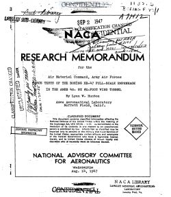
National Advisory Committee for Aeronautics, Research Memorandum - Force Tests of the Boeing XB-47 Full-Scale Empennage in the Ames 40 by 40 Foot Wind Tunnel
Presented in figure 1 is a three—view drawing of the model.
The body, which was _of a reinforced steel shell construction,
was de_signed and bu_ilt by the contractor to simulate the tail
cone of the XE—k? airplane. On this body were mounted the
actual horizontal and vertical tail surfaces from the first
.experimental_ XE—u? airplane. The installation of—the model in
the tunnel test section is shown in figure 2. Due to the
height of the vertical tail the model had to be mounted
approximately 7 feet below the center line of the air stream
in order to obtain the desired angle-cf—attack range. Such
a deviation from a normal test installation required a special
set of support struts as shown in figure 2. Since the drag
forces in this investigation were of little importance, no
attempt was made to shield these special struts with fairings.

The elevator and rudder were both constant~percent chord
(0.30) with an internal balance panel linkage as shown in -
figure 3. Both the horizontal and vertical surfaces employed
an NASA 65010 airfoil section (measured parallel to wind axis)
with cusps removed.' The control—surface movement and position
indication were effected by electric actuators and selsyns
which were installed in the control system. Deflections of
the right elevator tab (left tab locked in neutral for all
tests) were obtained by locking the tab in various fixed
positions. The rudder tab, however, was controllable remotely
with an actuator. The modifications tested included a bulged
trailing edge and a reduced hinge-line gap on the elevator and
a bulged tab on the rudder. Details of these modifications
are given with the test results.

FileAction
naca-rm-a7h12 Force Tests of the Boeing XB-47 Full-Scale Empennage in the Ames 40 by 40 Foot Wind Tunnel.pdfDownload 

Comment On This Post

Your email address will not be published. Required fields are marked *

naca-rm-a7h12

  • Version
  • 95 Downloads
  • 3.06 MB File Size
  • 1 File Count
  • April 20, 2017 Create Date
  • April 20, 2017 Last Updated
Scroll for Details

National Advisory Committee for Aeronautics, Research Memorandum - Force Tests of the Boeing XB-47 Full-Scale Empennage in the Ames 40 by 40 Foot Wind Tunnel

Presented in figure 1 is a three—view drawing of the model.
The body, which was _of a reinforced steel shell construction,
was de_signed and bu_ilt by the contractor to simulate the tail
cone of the XE—k? airplane. On this body were mounted the
actual horizontal and vertical tail surfaces from the first
.experimental_ XE—u? airplane. The installation of—the model in
the tunnel test section is shown in figure 2. Due to the
height of the vertical tail the model had to be mounted
approximately 7 feet below the center line of the air stream
in order to obtain the desired angle-cf—attack range. Such
a deviation from a normal test installation required a special
set of support struts as shown in figure 2. Since the drag
forces in this investigation were of little importance, no
attempt was made to shield these special struts with fairings.

The elevator and rudder were both constant~percent chord
(0.30) with an internal balance panel linkage as shown in -
figure 3. Both the horizontal and vertical surfaces employed
an NASA 65010 airfoil section (measured parallel to wind axis)
with cusps removed.' The control—surface movement and position
indication were effected by electric actuators and selsyns
which were installed in the control system. Deflections of
the right elevator tab (left tab locked in neutral for all
tests) were obtained by locking the tab in various fixed
positions. The rudder tab, however, was controllable remotely
with an actuator. The modifications tested included a bulged
trailing edge and a reduced hinge-line gap on the elevator and
a bulged tab on the rudder. Details of these modifications
are given with the test results.

FileAction
naca-rm-a7h12 Force Tests of the Boeing XB-47 Full-Scale Empennage in the Ames 40 by 40 Foot Wind Tunnel.pdfDownload 
17,005 Documents in our Technical Library
2464368 Total Downloads

Search The Technical Library

Newest Additions

NASA-RP-1060 Subsonic Aircraft: Evolution and the Matching of Size to Performance
AA-CP-20212-001
AA-CP-20212-001
ADPO10769 Occurrence of Corrosion in Airframes
The purpose of this lecture is to provide an overview ...
MIL-STD-1759 Rivets and Rivet Type Fasteners Preferred for Design
The purpose of this book form standard is to provide ...
MIL-STD-810G Environmental Engineering Considerations and Laboratory Tests
This standard contains materiel acquisition program planning and engineering direction ...