This is a method that can be used to reduce the apparent high stresses caused by geometric stress concentrations in fine mesh FE models with linear material properties……which is quite a mouthful.
In my few years in the analysis trade I have noticed that structures, despite the advances in analysis tools, have not been getting much lighter. In part this is due to inexperience with interpreting static analysis models. It is easy now to create a quick fine mesh model and check your stresses for the critical case, size the part and move on to the next bracket or fitting. However, these quick linear static analyses include geometric Kt effects and report high elastic stress values. Using these stress results to size the component or select a material is incorrect. It will be conservative and the part will be heavy.
If you were to size the same component with a hand analysis you would calculate the properties at a section, apply the loads and moments by hand, maybe calculate the principal stresses and use that resulting value to size to. Nowhere in the hand analysis would you take account of Kt effects and you would also consider using plastic bending effects (Cozzone) where appropriate to reduce peak linear bending stress values. A linear static FE model include KT effects and does not account for material plasticity.
Common features will have a Kt of 3 or greater – if your field stress is at an ultimate value of 50ksi (which can be matched using a hand analysis) you will be fine for most aluminum alloys, a fine mesh model with a hole will report at least 150ksi, only because of the geometry of the hole and the stress concentration created by that geometry.
There are two problems with this
- In the real world, if you are using a common aluminum alloy, the stress will be reduced by plastic redistribution which is fine for an ultimate level check
- You should not consider Kt effect for static analysis regardless
 So – how do you mitigate the Kt effects from linear static fine mesh model results?
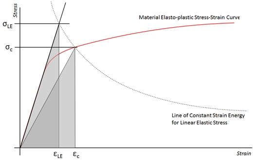
The triangular area of the strain energy under the elastic material line can be equated to the point where the line of constant strain energy related to the linear stress and strain crosses the elasto-plastic material curve.
This approach is slightly conservative as you could equate this to the total area under the elasto-plastic material curve which would further lower the corrected stress.
The Neuber method equates the areas of the two triangles to reduce the high elastic stress.
Note that this method does not remove the Kt effect per se, but it does remove the artificially high stress that the linear elastic model results report, and gives you the equivalent plastic stress at the peak linear stress location.
We have updated and improved our free spreadsheet to give the reduced Neuber stress here
This improved version of the spreadsheet automatically solves for the Neuber stress at the intercept between the line of constant strain energy and the elasto-plastic material curve.

To try our free Stress Analysis Engineering Spreadsheets click below

To try our Add-in for Microsoft Excel for Windows click below

Hello,
Your spreadsheet will suport me in some stress svaluations, tank you,
Please, what is the material property “n” in your spreadsheet.
Thanks in advance
Manoel,
‘n’ is the material shape factor used to construct the Stress-Strain curve using the Ramberg-Osgood method. You can read more about it in this post.
The shape factors in the yielding region can be found in Mil-Hndbk-5 or MMPDS at the end of each section.
Good luck!
Hello,
Does the Neuber method give useful results for multi-axial stress states?
The problem: a hollow rectangular section fixed at one end, loaded with a transverse load at the end, so shear stresses and bending stresses. Other resources state that it can only be used for uni-axial stresses. What’s your opinion?
Thanks a lot.
Alfred
The Netherlands
btw: great site!
Neuber should really be used at peak stresses created by Kts or stress-raising features. If you have a tube (with no features) in bending you should use cozzone plastic bending theory to account for stresses beyond Ftu for a simple linear elastic analysis – i.e. stresses from My/I. As the shear stress really peaks around the neutral axis of the bending section the peak axial stresses created by the bending effects do not really interact with a significant level of shear stress and so you can ignore the interaction of the transverse shear with the axial stresses created by the bending moment.
Glad you enjoy using the site!
Dear Richard,
Congratulations for your site, very helpful, you are doing a great job, thank you!.
Could you please generate a version of the spreadsheet to allow the user to enter stress data in units MPa as well as imperial units?, thanks!.
When I open the spreadsheet I see the XYPLOT with the Y-vertical axis named “Stress (MPa)”, but the values are so high, then not correct.
Best regards form Spain, Merry Xmas & Happy New Year!!.
Blas.