You can read the first two posts in this series here:
Post 1, Post 2
When you calculate a buckling allowable that is beyond the material shear yield stress the allowable is unrealistic. For shear buckling this can be particularly problematic as the shear yield strength is not typically given in the common material data set so it can be difficult to know when it has been exceeded.
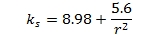
There is a method given in chapter 9 of (MIL-HNDBK-5H, 1998) for estimating the shear yield strength of a material:

Once you have the shear yield strength you have a rough idea of if your buckling allowable is in the plastic or elastic range of the material.
The simplest way to account for material plasticity is to limit the allowable to the shear yield strength. This is not very accurate, it can be either optimistic or conservative depending on the magnitude of the calculated elastic allowable, but it is ‘reasonable’ – we will do a comparison later in this post.
The better way to account for material non-linearity is to use the secant modulus, specifically the secant shear modulus Gs.
The secant shear modulus is given by the following expression:
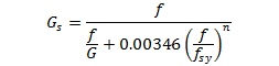
Where f is the applied stress and fsy is the shear yield stress and n is the Ramberg-Osgood Shape Factor.
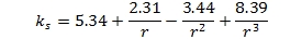
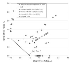
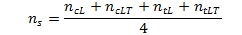
To determine the shape factor for the shear stress/strain curve the following expression can be used as long as the traditional extensional shape factors are known.
The plastic material correction factor for shear buckling is Gs/G
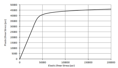
We construct a graph of that relates the linear shear buckling allowable to the Gs/G modified plastic buckling allowable. For a sample aluminum material that curve looks like this:
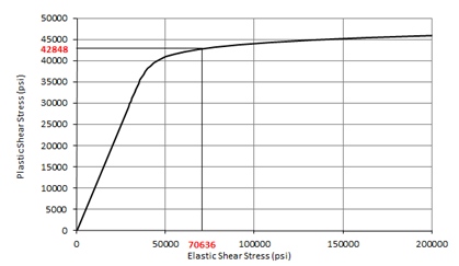
Once you have constructed this curve you can plot the elastic buckling stress on the x-axis, project a line up to the curve and read the corrected plastic buckling stress from the Y axis:
This curve can also be used to compare the simple approach of using the shear yield stress value as a simple cutoff value for the elastic stress: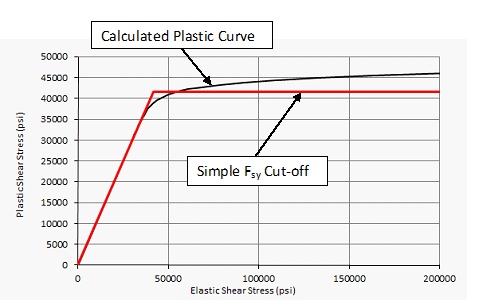
For most aluminums the simple approach of using the Fsy value as a cut off value for shear buckling is appropriate for initial sizing.
As with all of the methods we use on a regular basis we have created a spreadsheet for full elasto-plastic shear buckling and you can down load it here
We also have a spreadsheet that calculates full range stress-strain curves and elasto-plastic buckling allowable curves for common buckling modes.
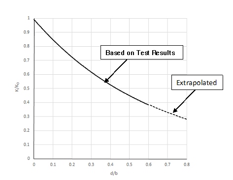
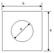
In the next post we will cover how to account for the presence of a hole in a shear panel.

To try our free Stress Analysis Engineering Spreadsheets click below

To try our Add-in for Microsoft Excel for Windows click below

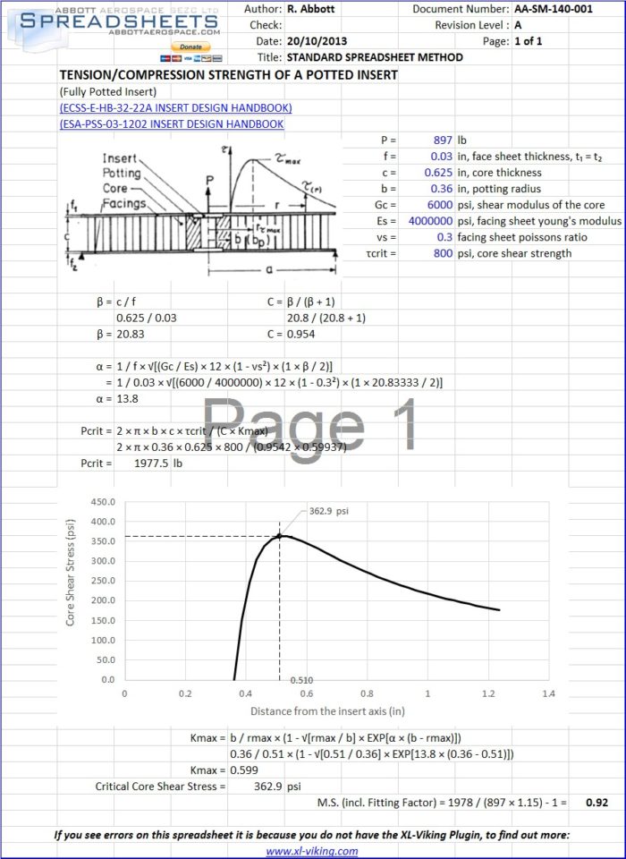 As we go through the process of up loading all of our reference data to the library we can also complete uploading the linked and referenced spreadsheet methods. We have just uploaded our ECSS references so we have linked and uploaded our potted insert analysis spreadsheets.
 These spreadsheets are numbered
 There are limited options for dealing with a hole in a shear web. There is a often used ESDU reference for this situation. ESDU sheets are a commercial product and unless you, or your organization have paid for them, you should not use them.