Shear Stress Distributions

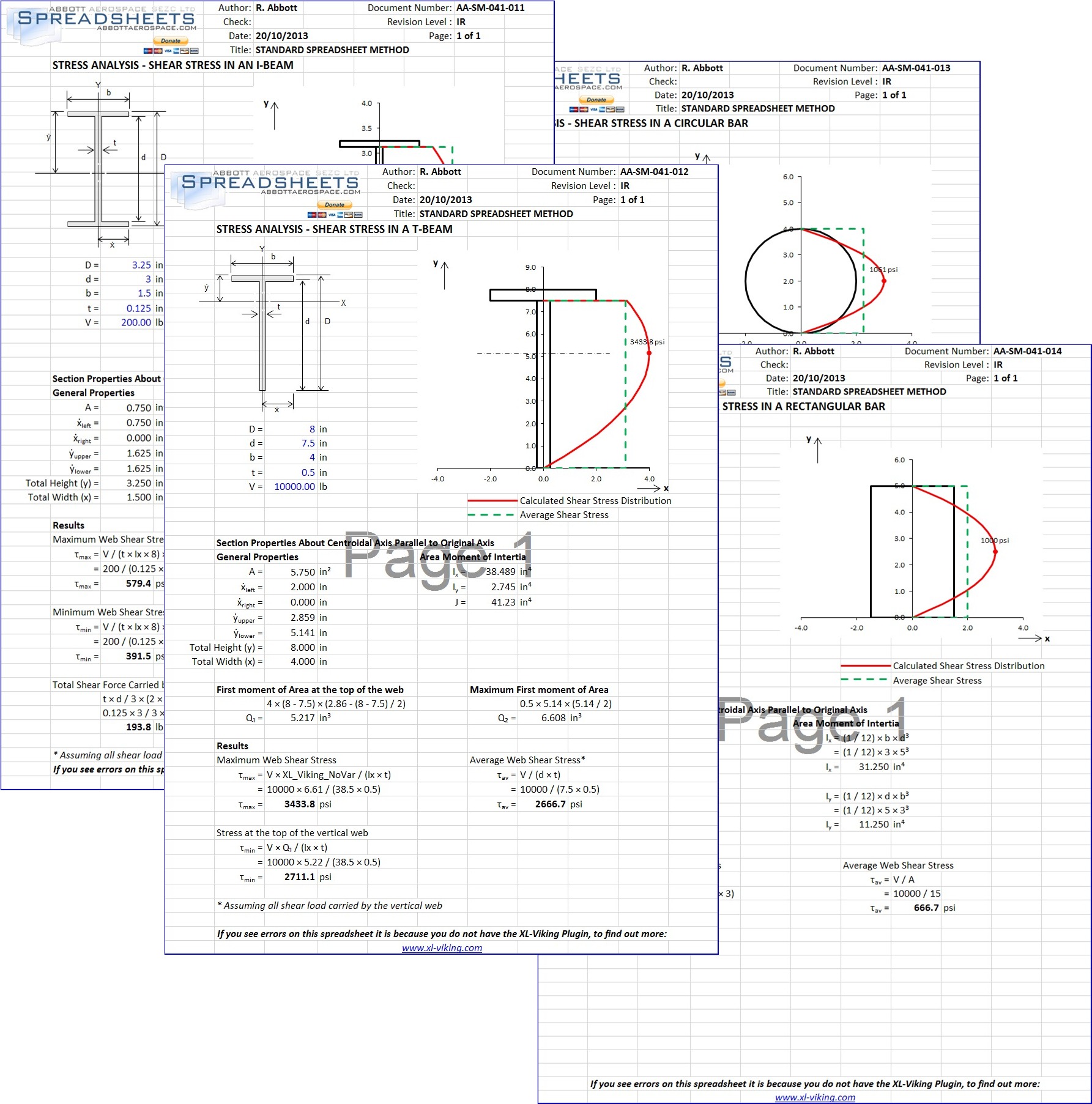
In the course of developing a new a comprehensive set of section properties for common cross sections I started to look into the first moment of area of cross sections. This led me to calculating the shear stress distributions. Typically when an engineer is calculating shear stress in a cross section they calculate the average shear stress in the cross section (or at least in the component of the cross section aligned with the shear load such as the web of an I section).

For a material in the elastic range the shear stress distribution is not linear and has a higher peak shear stress than the average shear stress. This shear stress distribution relies on the first moment of area.

We have posted 4 spreadsheets that calculate the true shear stress distributions for common beam cross sections at these links:

AA-SM-041-014 Free Engineering Spreadsheets: Stress Analysis – Shear Stress in a Rectangular
AA-SM-041-013 Free Engineering Spreadsheets: Stress Analysis – Shear Stress in a Circular Bar
AA-SM-041-012 Free Engineering Spreadsheets: Stress Analysis – Shear Stress in a T-Beam
AA-SM-041-011 Free Engineering Spreadsheets: Stress Analysis – Shear Stress in an I-Beam

Textbook Update

In the final checking stage of the creation of our Design and Analysis textbook we have changed the structure of the book. The intent of this change is to use the content we have already created in a more comprehensive content structure. This should make the book more ‘future proof’.

The book is created and distributed (for free) in a way that allows us to make regular updates and improvements. Our current plan is to issue a new edition of the book on at least an annual basis. The risk of doing this is that changes to the text of the book may force renumbering of existing sections in the book. This would invalidate existing citations to numbered subsections of the book.

Taking this approach now means that initial editions of the book will have empty chapters. However, the chapter titles will give the reader/user an idea of the content that we will add in the future.

This may cause a delay in the final publication of the first edition, but we are working hard to get the book revised, checked and released by the end of August.

We appreciate your patience and all of the encouragement we have received so far.


Update to this post: The Textbook is now available for download here


Panel Buckling Edge Rotational Restraint – Spreadsheet Method

As part of our series of buckling analysis spreadsheet methods we have defined a quantifiable method for calculating a numerical value for panel edge rotational restraint that can be used in the standard buckling analysis methods. This method draws from a theory defined in (NACA-REPORT-735, 1942) and (NACA-TN-888, 1943).

This method includes a calculation of a little used section property called the Torsion-Bending constant:

CBT Equation

where u is the unit warping of the element of area dA from a reference plane through the shear center and normal to the axis when the angle of twist per unit length  is unity

Thankfully the references give a rational method for common cross section, this calculation is included in the spreadsheet.

The Spreadsheet is available here: AA-SM-007-070

Let us know what you think in the comments section below, enjoy!


NASA Releases High Resolution 3D Scan of Apollo 11 Command Module

NASA and the Smithsonian Museum have made available a high resolution 3D scan of the Apollo 11 Command module which is made up of over a trillion points. You can view it here. Screenshot of the version available on the web is shown above.  Downloadable models are available on the main page here.

47 years ago we landed on the moon.  Admiration and support are due to those among us who are trying to get us back to the moon and beyond.
Apollo 11 Scan


Lug Analysis Spreadsheets

We have updated the lug methods for our engineering textbook and one of the best explained and best laid out classic lug analysis comes from the US Airforce Stress Manual, AFFDL-TR-69-42  and is explained in our online textbook here. We have used this as the basis for our lug analysis spreadsheets. All of the curves are fully digitized. There is a spreadsheet for each of the individual failure modes :

AA-SM-009-001 Lug Analysis – Shear Bearing Strength.xlsx

AA-SM-009-002 Lug Analysis – Axial Strength.xlsx

AA-SM-009-003 Lug Analysis – Transverse Strength.xlsx

and there is a fully automated sheet that does all of the calculations and calculates the interaction:

AA-SM-009-005 Lug Analysis – Compact Oblique.xlsx

There is also a spreadsheet that calculates the complex pin bending effect.

AA-SM-009-004 Lug Analysis – Pin Bending.xlsx

Enjoy!


Membrane Analysis Spreadsheets

AA-SM-013-053It has been a few weeks since we posted any new analysis spreadsheets. We have been busy getting the check version of the engineering textbook ready for the mailing list subscribers which was finally released in the June newsletter.

Along the way we did manage to create some analysis spreadsheets of the membrane analysis methods in AFFDL-TR-69-42 .

AA-SM-013-051 Circular Membranes.xlsx

AA-SM-013-052 Long Rectangular Membranes.xlsx

AA-SM-013-053 Short Rectangular Membranes.xlsx

Enjoy!


Landing Gear – Rational Spin-Up and Spring-Back Loads – Update


This is an update to a previous post here. During further background reading I came across this reference ARC-RM-2588 which gives a more detailed method for developing spin-up loads for aircraft landing gear. When I get time I will see if it is worth adding as an alternative spreadsheet method to the library and run some comparisons to the NACA method (NACA-TN-863).