Stratos Wing Test

This article first appeared in the December 2017 edition of our free newsletter, to subscribe click here


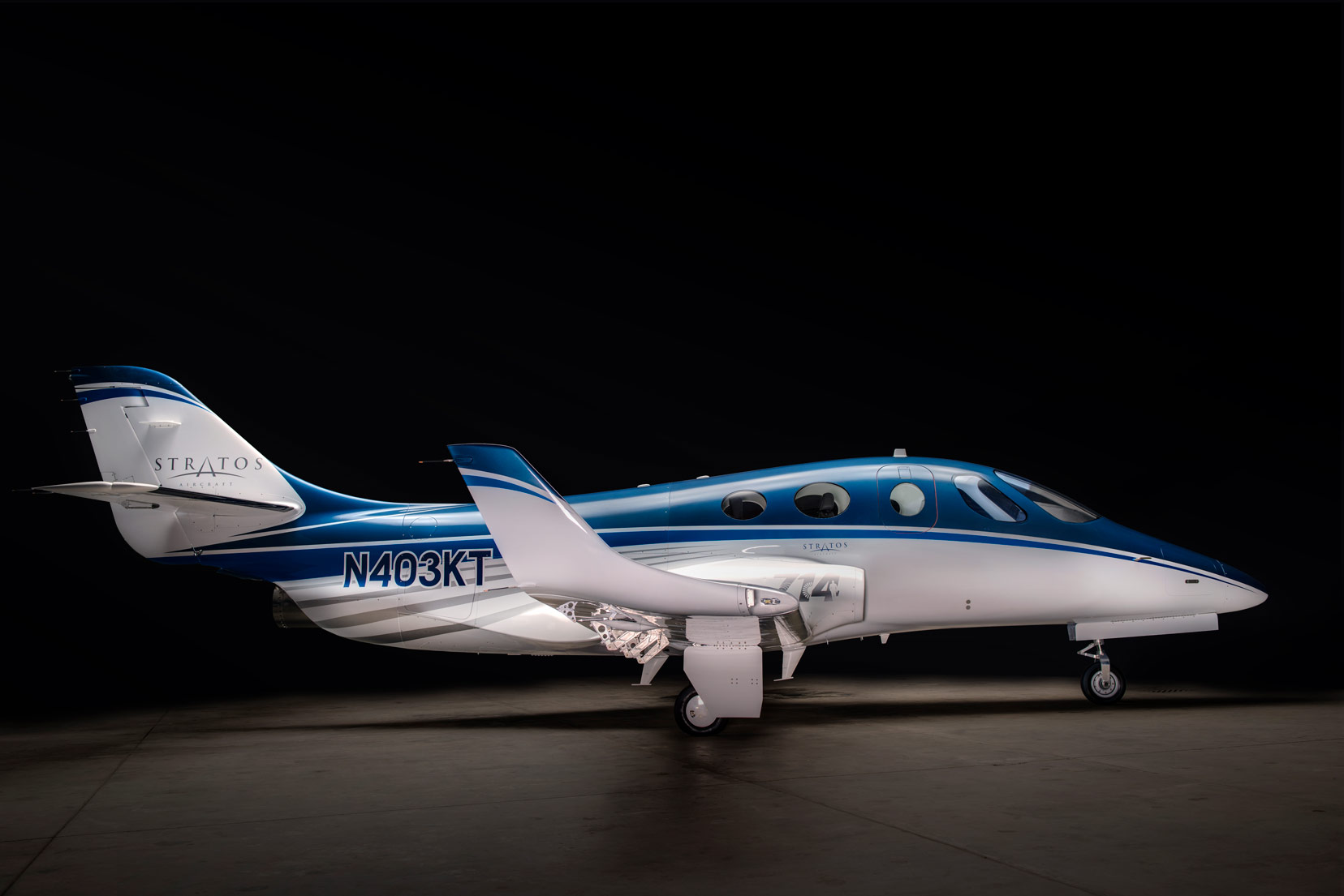
In December I flew to Redmond Oregon to spend some quality time with the Stratos Aircraft project. Nirav Shukla and I have worked on the production version of the wing for the Stratos 714 jet and the wing test article has been constructed over the last few months.

I can’t give specific figures but we reduced the weight of the wing by several hundred pounds compared to the prototype aircraft wing. This was, in part, relatively easy because there is never enough time in a prototype program to get the structure to the target weight – so there was some low hanging fruit. However, we were happy with the result and the test went very well and we are comfortable with the strength of the structure and Stratos is happy with the weight. All good!

Between the prototype and the production design, we upgraded the FE model of the wing – and the whole aircraft.

In the finite element model of the prototype, we modeled all of the cored composites with single laminate element cards. This creates large offsets relative to the element size:

Laminate elements can become unreliable as the offset approaches the element size, especially so for asymmetric layups.

We changed the finite element mesh to the following configuration:

The core is modeled with solid elements and the laminate elements have a much smaller offset relative to their element size. This means that we could increase the mesh density without compromising the veracity of the solution.

We could also model features such as core chamfers more accurately.

Wing Upper skin showing laminate Element Thicknesses


View on the underside of the upper skin showing modeled Core Features


Because of the increase in mesh density we have a greater trust in the buckling solution from the finite element model so we could move away from hand buckling checks that we knew to be very conservative to using the finite element solution for buckling.

In using the large assembly and global FE model for buckling we saw buckling results that we knew were likely to be ‘non-real’. These were compression buckling modes that were centered on the node at the bottom of the core chamfer and were very local to that region of the panel.


Typical compression buckle at core ramp down

We still made sure that these modes occurred above 150% of limit load. We were happy with a zero margin of safety for these buckling loads as we did not expect to see them on test and we did not see any sign of them on test.

If you have any experience of this behavior from this type of modeling we would love to hear from you to compare notes.

The wing attachment bracket regions were sized using typical hand methods available in our technical library.

Yours truly in front of the wing mounted in the test rig just before the test was done

The test went very well. Dieter Kohler was on hand to conduct the test. It is much better to have an independent expert conduct the test. As it is ‘our wing’ if I were conducting the test we would have stopped at every noise coming out of the wing box. Dieter ran the test up to limit and then from zero to limit and finally ultimate briskly, largely ignoring the few noises that came out of the wing box.

On post-test inspection the integrity of the wing box was not compromised. There were some minor hairline adhesive cracks at a couple of locations. These cracks may have been present before the test – the scrutiny that an assembly is subjected to post-test is much higher than the inspection before the test and the cracks were so small that they may be been missed by the pre-test inspection.

In the end, it should have come as no surprise that the wing passed the test – we are using strain limits that give very high residual strength for the undamaged structure.

After a series of other tests (static loading of the MLG in the wing, testing of the flap on the wing, internal pressure testing) we will be able to play with the wing – induce some damage and find out what the true residual strength of the wing is by testing to destruction. The fun stuff!

Note: the test documented in this article and the planned series of tests are internal company development tests and will not be used for certification of the aircraft.

Thanks to Stratos Aircraft for first of all including us in the development team for their fantastic aircraft and for allowing us to publish this article.

Comment On This Post

Your email address will not be published. Required fields are marked *