A version of this article first appeared in the July 2019 edition of our free newsletter, to subscribe click here
We are at the stage of building out UAV, that if I were to show any more photographs I would be giving too much away. However – I can talk about what I have learned and how we are changing the detailed design of the next version of the UAV to make better use of the unique nature of the 3D printing progress.
Previously I took a traditional frame and skin approach, making the skin removable to allow access to the interior. This means the main body of the UAV comprises of over 20 parts, 5 of these are removable skin panels.
For version 3.0 (better configuration: lower drag, more stability on the ground, more useful internal volume) I have modified the main body. It is made up of 4 major components with 4 removable access panels.
I can show a single component without giving too much away
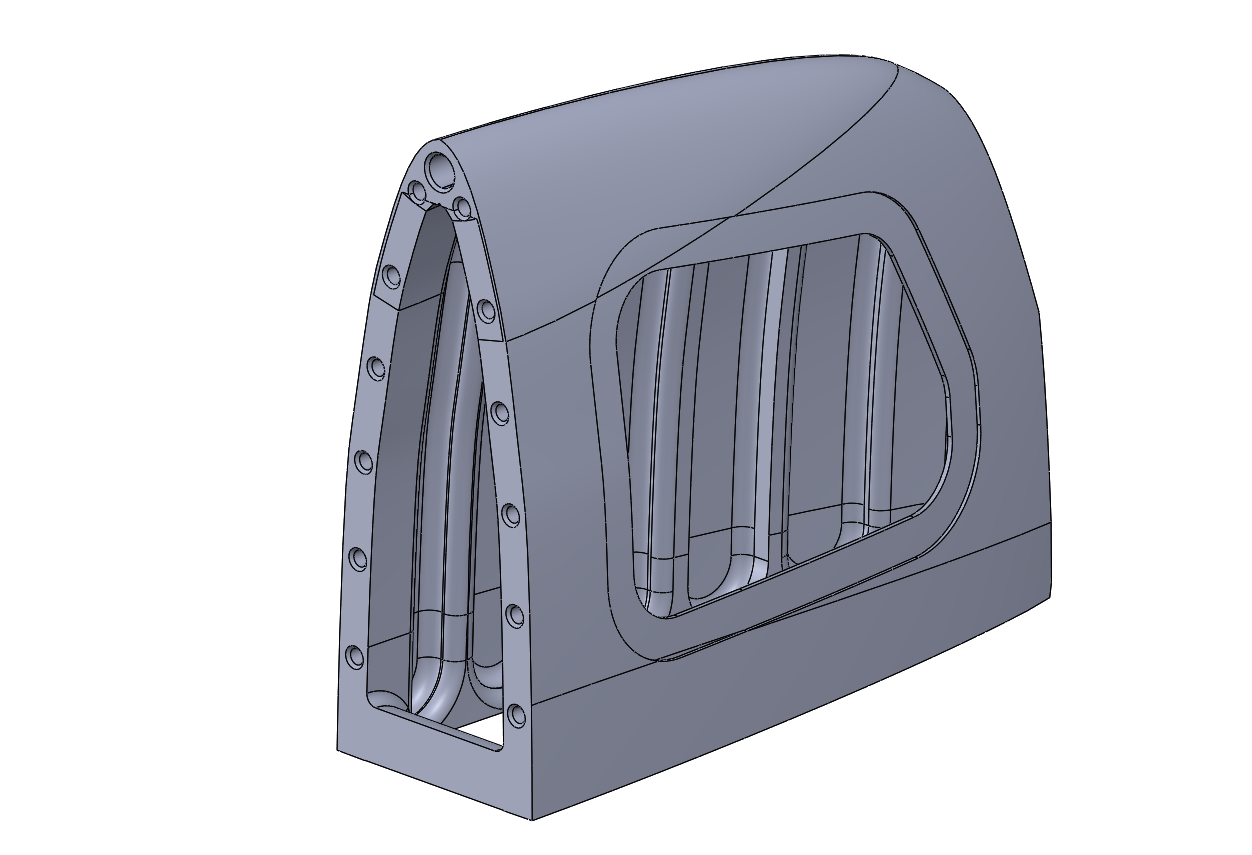
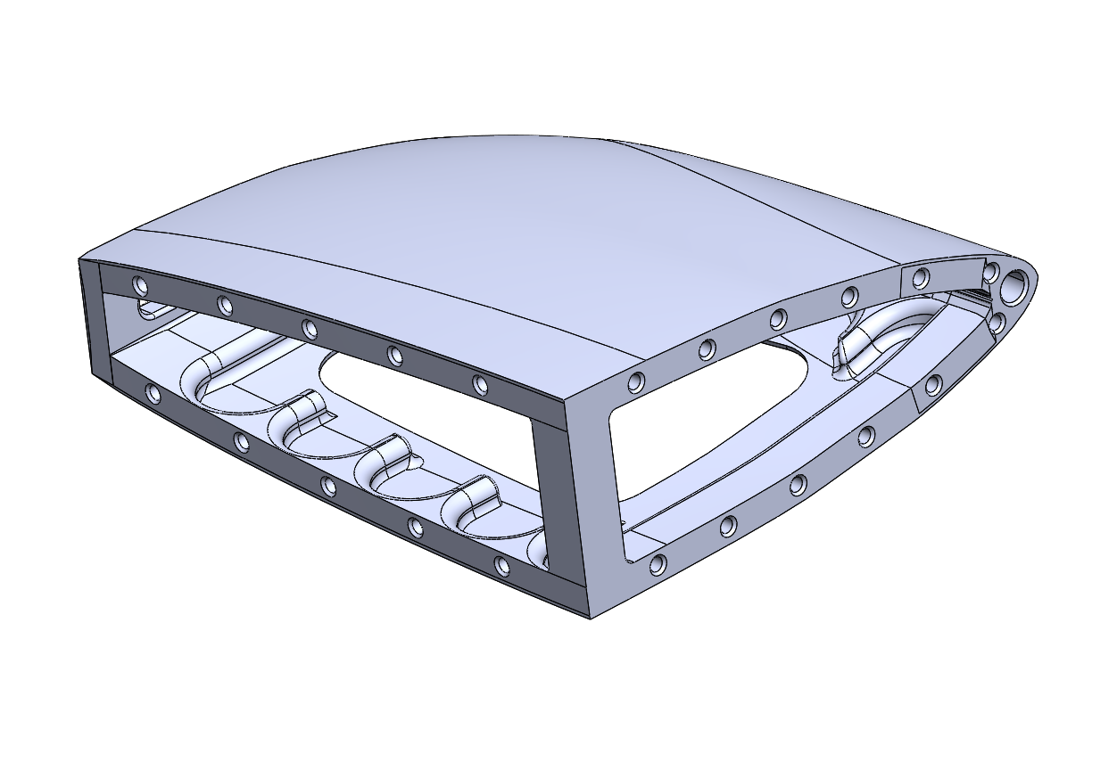
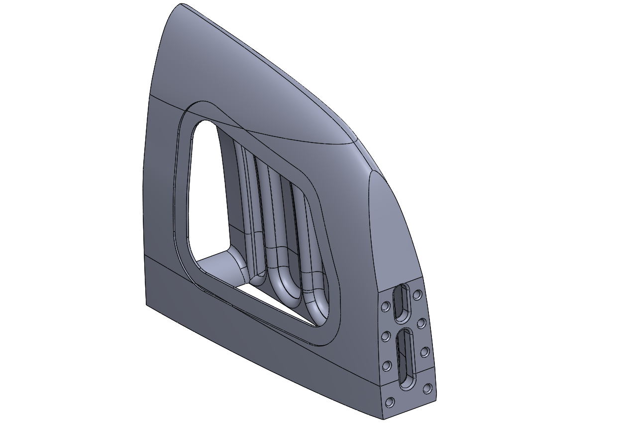
This is one ‘chunk’ of the main body. The holes on the flat mating faces are for dowels. For the permanently joined interfaces we are going to use multiple bonded dowel rods (and adhesive on the mating flat faces) to give good shear and tension strength.
These dowels can be wooden or stock carbon tubes. For the first build of the V3.0 UAV we will probably use wooden rods from the local hardware store. Very ‘Ikea’ and very strong.
We will take full advantage of the in-fill capabilities of 3D printing with integrated cored stiffeners
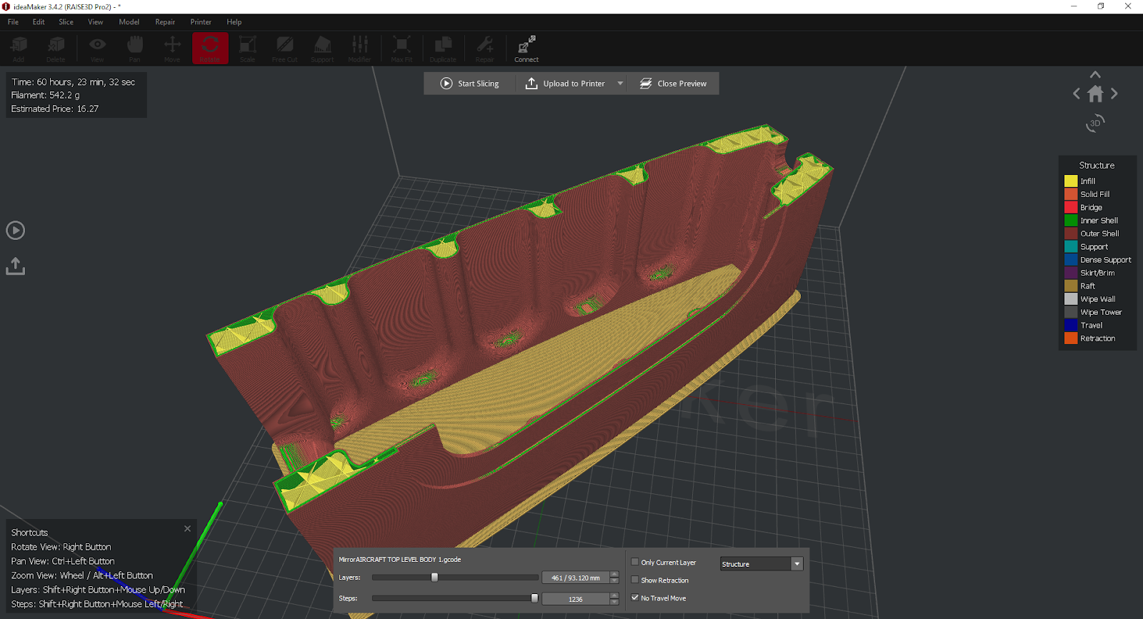
We are also working on creating designs that need no or minimal support structures. This reduces the printing time significantly, increases the surface finish quality and reduces the amount of hand finishing that is required
Once we have the current UAV (Version 2.0) built we can start work on the V3.0 and overall the build time should reduce by 50%.
The weight should be similar and the vehicle will be much better overall.
It is proving very valuable to run through sub assembly design-manufacture iterations inside our own office in a matter of days or weeks. Someday all aircraft development will be like this……..
Interested as to whether you need to have stiffners in the access panel and if the load path through the stiffners of the body is to pass around the opening of the access panel through use of increased thickness.
.
Also, you intend to make use of the shear strength of the adhesive to react tensile loads ? I’m guessing these loads aren’t considerable if you’re not using a mechanical fastening method as your primary means of holding the sections together.
.
The dowels (biscuits and or Dado joints) will provide for great resistance to shear across their cross section but they aren’t efficient when it comes to resisting tensile forces.
.
I do however concede that you might be intending to use a series of dowels ( biscuits and or Dado joints) installed at right angles to react loads primarily via the material and not the adhesive.
.
I’m just thinking aloud and I’m sure you’ve sorted the joint configuration out to satisfaction already.
.
…
The plan is to have the access panel non structural – then any external sensor can be mounted within a custom access panel
The bonded joint with dowels makes the most of the shear strength of the adhesive – I am confident it will be ‘Strong like Bull’
Glue is ‘dodgy’ (as you know, very process dependent) dowels and biscuits help increase the surface area overall and reduce your statistical chance of a critical processing issue…..
We will see – it is nice to get to physically prototype stuff myself. I finally get to put my money where my mouth is.