NASA-CR-182018

NASA-CR-182018
  • Version
  • 290 Downloads
  • 1.56 MB File Size
  • 1 File Count
  • March 29, 2016 Create Date
  • March 29, 2016 Last Updated
Scroll for Details

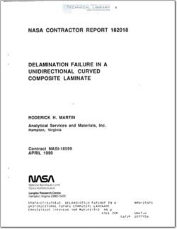
Delamination Failure in a Unidirectional Curved Composite Laminate
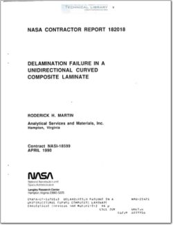
NASA-CR-182018 Delamination Failure in a Unidirectional Curved Composite Laminate

ABSTRACT

This paper investigated delamination failure in a unidirectional curved
composite laminate. The curved laminate failed unstably by delaminations
developing around the curved region of the laminate at different depths
through the thickness until virtually all bending stiffness was lost.
Delamination was assumed to initiate at the location of the highest radial
stress in the curved region. A closed form curved beam elasticity solution
and a 2-D finite element analysis (FEA) were conducted to determine this
location. The variation in the strain energy release rate, G, with
delamination growth was then determined using the FEA. A strength-based
failure criterion adequately predicted the interlaminar tension failure which
caused initial delamination onset. Using the G analysis the delamination was
predicted to extend into the arm and leg of the laminate, predominantly in
mode I. As the initial delamination grew around the curved region, the
maximum radial stress in the newly formed inner sublaminate increased to a
level sufficient to cause a new delamination to initiate in the sublaminate
with no increase in applied load. This failure progression was observed

experimentally.

INTRODUCTION

With the increased use of laminated fiber reinforced composite materials
in primary aircraft structural components, the ability to understand and
predict their failure modes becomes paramount. Because of the low
through-the-thickness strengths of composites one of their prime modes of
failure has been delamination [l]. The high interlaminar stresses which may

cause delamination can arise from material discontinuities, geometric

discontinuities, or eccentricities in the load path. One example of a generic
structural component which has the possibility of all three of these
interlaminar stress sources is the curved laminate. Some typical uses of a
curved composite laminate are shown in fig. 1. Mostly, the laminates are of a
multidirectional layup. The material property mismatch between adjacent plies
of different orientation may create singular interlaminar stresses at the free
edge causing edge delamination [2]. Another failure mode occurs when the
membrane stresses in off-axis plies are high and cause transverse tension
cracking across the width [3]. Mathematically singular interlaminar stresses
may occur where the matrix crack meets the adjacent plies. These stresses may
cause delamination at this location. Delamination may also occur as an
interlaminar tension failure caused by tensile radial stresses created from
the bending of the curved laminate.

Several studies in the literature have focused on determining damage in
curved laminates. In reference 4, a finite element analysis was used to
determine the strain distribution for the design of curved composite frames
for the UH60 Black Hawk Helicoptor. In reference 5, a strength—based
criterion based on the Tsai-Hill criterion was used to predict if an off-axis
ply failure or an interlaminar tension failure would occur in multidireCtional
curved laminates. In reference 6, a finite element analysis and a closed-form
solution was conducted to determine 'the stress distribution in a curved
composite frame taken from the V22 Osprey. The Tensor Polynomial criterion
was used to predict failure. In reference 7, an elasticity solution was used
to determine the stress distribution in a semi-cirtular composite beam. In
reference 8, composite angles of different lay-ups were tested and analysed.

FileAction
NASA-CR-182018 Delamination Failure in a Unidirectional Curved Composite Laminate.pdfDownload 

Comment On This Post

Your email address will not be published. Required fields are marked *

NASA-CR-182018

NASA-CR-182018
  • Version
  • 290 Downloads
  • 1.56 MB File Size
  • 1 File Count
  • March 29, 2016 Create Date
  • March 29, 2016 Last Updated
Scroll for Details

Delamination Failure in a Unidirectional Curved Composite Laminate

NASA-CR-182018 Delamination Failure in a Unidirectional Curved Composite Laminate

ABSTRACT

This paper investigated delamination failure in a unidirectional curved
composite laminate. The curved laminate failed unstably by delaminations
developing around the curved region of the laminate at different depths
through the thickness until virtually all bending stiffness was lost.
Delamination was assumed to initiate at the location of the highest radial
stress in the curved region. A closed form curved beam elasticity solution
and a 2-D finite element analysis (FEA) were conducted to determine this
location. The variation in the strain energy release rate, G, with
delamination growth was then determined using the FEA. A strength-based
failure criterion adequately predicted the interlaminar tension failure which
caused initial delamination onset. Using the G analysis the delamination was
predicted to extend into the arm and leg of the laminate, predominantly in
mode I. As the initial delamination grew around the curved region, the
maximum radial stress in the newly formed inner sublaminate increased to a
level sufficient to cause a new delamination to initiate in the sublaminate
with no increase in applied load. This failure progression was observed

experimentally.

INTRODUCTION

With the increased use of laminated fiber reinforced composite materials
in primary aircraft structural components, the ability to understand and
predict their failure modes becomes paramount. Because of the low
through-the-thickness strengths of composites one of their prime modes of
failure has been delamination [l]. The high interlaminar stresses which may

cause delamination can arise from material discontinuities, geometric

discontinuities, or eccentricities in the load path. One example of a generic
structural component which has the possibility of all three of these
interlaminar stress sources is the curved laminate. Some typical uses of a
curved composite laminate are shown in fig. 1. Mostly, the laminates are of a
multidirectional layup. The material property mismatch between adjacent plies
of different orientation may create singular interlaminar stresses at the free
edge causing edge delamination [2]. Another failure mode occurs when the
membrane stresses in off-axis plies are high and cause transverse tension
cracking across the width [3]. Mathematically singular interlaminar stresses
may occur where the matrix crack meets the adjacent plies. These stresses may
cause delamination at this location. Delamination may also occur as an
interlaminar tension failure caused by tensile radial stresses created from
the bending of the curved laminate.

Several studies in the literature have focused on determining damage in
curved laminates. In reference 4, a finite element analysis was used to
determine the strain distribution for the design of curved composite frames
for the UH60 Black Hawk Helicoptor. In reference 5, a strength—based
criterion based on the Tsai-Hill criterion was used to predict if an off-axis
ply failure or an interlaminar tension failure would occur in multidireCtional
curved laminates. In reference 6, a finite element analysis and a closed-form
solution was conducted to determine 'the stress distribution in a curved
composite frame taken from the V22 Osprey. The Tensor Polynomial criterion
was used to predict failure. In reference 7, an elasticity solution was used
to determine the stress distribution in a semi-cirtular composite beam. In
reference 8, composite angles of different lay-ups were tested and analysed.

FileAction
NASA-CR-182018 Delamination Failure in a Unidirectional Curved Composite Laminate.pdfDownload 
17,005 Documents in our Technical Library
2797808 Total Downloads

Search The Technical Library

Newest Additions

NASA-RP-1060 Subsonic Aircraft: Evolution and the Matching of Size to Performance
AA-CP-20212-001
AA-CP-20212-001
ADPO10769 Occurrence of Corrosion in Airframes
The purpose of this lecture is to provide an overview ...
MIL-STD-1759 Rivets and Rivet Type Fasteners Preferred for Design
The purpose of this book form standard is to provide ...
MIL-STD-810G Environmental Engineering Considerations and Laboratory Tests
This standard contains materiel acquisition program planning and engineering direction ...