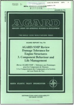
AGARD-R-770

- Version
- 185 Downloads
- 54.80 MB File Size
- 1 File Count
- April 12, 2016 Create Date
- April 12, 2016 Last Updated
Damage Tolerance for Engine Structures 3. Component Behaviour and Life Management

This third AGARD workshop on damage tolerance concepts for gas turbines considers
how the specific needs of the component can be taken into account, how the type of
mission flown affects the approach taken, the role of in flight monitoring and
life management planning. These considerations are required to produce positive
life and integrity statements from an understanding of the component condition
gained using the inspection techniques discussed in workshop 1, and our fundamental
knowledge of materials and defect behaviour covered in Workshop II.
Components in service engines behave differently from laboratory specimens of the
same material (even when cut from the components concerned) for the following
reasons.
The component stress/strain/time/temperature operating envelope is insufficiently
well defined.
The multi-axial stress/strain conditions created by the geometry of the component
features are insufficiently understood.
The missions flown deviate from those considered in the component life analysis
either due to complexity that cannot be covered by the techniques available or
to the engine being flown through missions that were not initially envisaged.
Changes due to time or environment invalidate the initial assumptions of
component condition and behaviour eg. material instability, oxidation and
corrosion.
Surface damage occurs, eg. fitting damage, frettage, foreign object damage,
invalidating the assumptions regarding initial material condition.
Above all the use of forgiving materials, within a limited performance envelope and
with large "safety" factors, has, in the main, avoided failures due to our lack of
knowledge of materials and component behaviour.
The demands for higher performance engines of lower weight and longer life, all at
lower cost, are forcing the designer to eat into these margins hence the need to '
reduce the degree of uncertainty in the knowledge of materials, component and engine
behaviour.
This nowadays tends to be a two dimensional or three dimensional elastic finite
element model which is used to calculate stresses and deflections at features
and in plane sections.
The component however behaves as a three dimensional, plastic, time-dependant
entity, especially at features. Factors such as creep and plastic deformation
are becoming important in components such as discs where fatigue was considered
dominant. Cyclic behaviour, especially thermal fatigue, is important in
thermal stressed components such as turbine blades and combustors where creep
ruled supreme (Fig 1).
| File | Action |
|---|---|
| AGARD-R-770 Damage Tolerance for Engine Structures 3. Component Behaviour and Life Management.pdf | Download |
Comment On This Post